1 wiring connections, 2 constant setpoint mode configuration, 3 viewing constant set point – AERCO Modulex E8 Controller (and BCM) For Modulex EXT Boilers User Manual
Page 60: E8 controller and bcm for modulex ext
E8 Controller and BCM for Modulex EXT
Installation, Operation & Maintenance Manual
CHAPTER 6: E8 SETUP & PROGRAMMING
Page
60 of 108
AERCO International, Inc. • 100 Oritani Dr. • Blauvelt, NY 10913
OMM-0093_0A
PRI: 06/24/2013
Phone: 800-526-0288
GF-136-C
6.2.1 Wiring Connections
There are NO wiring connections required for this mode.
6.2.2 Constant Setpoint Mode Configuration
The Constant Setpoint Mode is enabled using functions contained in the EXPERT menu and
USER menu as shown on previous page.
6.2.3 Viewing Constant Set Point
The set point is viewed in the DISPLAY menu as shown below.
Viewing the Constant Setpoint
1. Use Rotary Knob to navigate to the
DISPLAY menu. First sub-menu displayed will be
INSTALLATION.
2. Press the Program Key to enter the
INSTALLATION sub-menu.
3. Turn Rotary Knob clockwise until T-COLL DES is displayed along with corresponding
temperature reading. This
T-COLL DES reading equals the boiler set point in °F.
6.2.4 Configuring Set Point High and Low Limits Per Outside Temperature Sensor
It is often desirable to control the maximum and minimum outlet water temperature based on
outside air temperature. For instance it might be desirable to set the outlet water temperature to
be 180º F whenever the outside temperature is 15º F or below, and 120º F whenever the
outside temperature is 60º F or higher. Four parameters must be set in the E8 Controller to
accomplish this. They are: HEATSLOPE, MAX T-FLOW, MIN T-FLOW, and MAX T-COLL.
Descriptions are provided in Table 6-1.
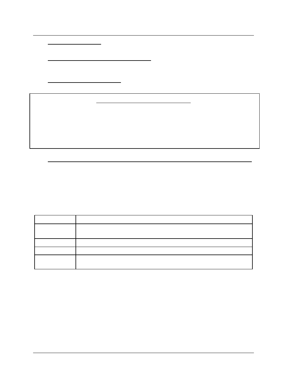
Table 6-1: E8 Controller Outside Temperature Sensor Parameters
Parameter
Description
HEATSLOPE A curve that relates a boiler’s outflow temperature with the outside air
temperature monitored with a temperature sensor
MAX T-FLOW The maximum allowable outlet water temperature
MIN T-FLOW The minimum allowable outlet water temperature
MAX T-COLL The maximum allowable outflow water collection manifold surface
temperature
To select the best HEATSLOPE value to enter into the E8 Controller, consider the set of heat
slope curves shown in Figure 6-1. Locate the two points given by the coordinate pairs (Outside
Temperature, Flow Temperature); One for the low temperature range and one for the high
temperature range. Now find the curve that best fits these two points. Do not expect any single
curve to go through either point, let alone both points. Simply pick the best fit.