E8 controller and bcm for modulex ext, Installation, operation & maintenance manual, Chapter 8: boiler communication module (bcm) – AERCO Modulex E8 Controller (and BCM) For Modulex EXT Boilers User Manual
Page 87
E8 Controller and BCM for Modulex EXT
Installation, Operation & Maintenance Manual
CHAPTER 8: BOILER COMMUNICATION MODULE (BCM)
OMM-0093_0A
AERCO International, Inc. • 100 Oritani Dr. • Blauvelt, NY 10913
Page
87 of 108
GF-136-C
Ph.: 800-526-0288
PRI: 06/24/2013
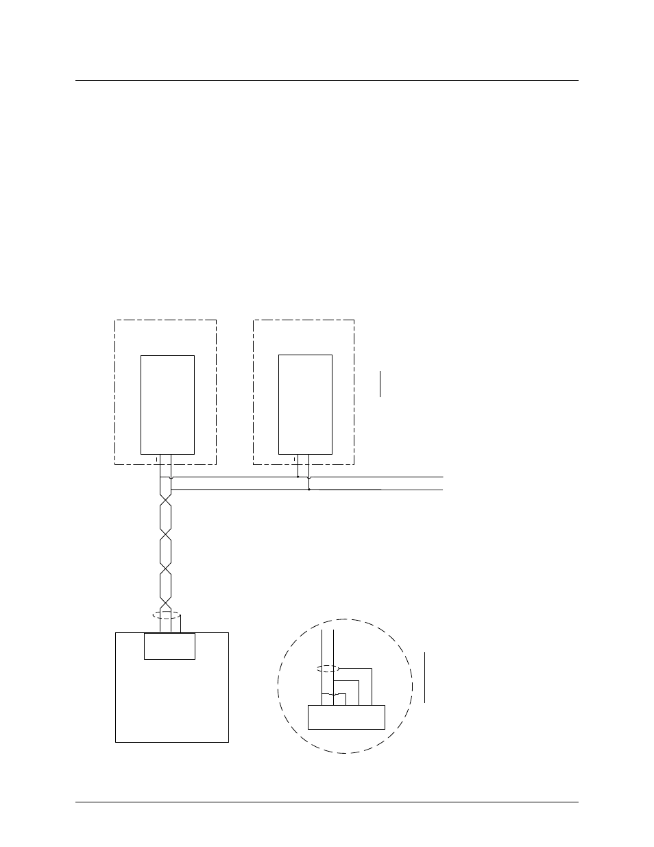
Figure 8-11 shows a Sample Modbus Network wiring diagram for a Master EMS/BAS controlling
BCM Controller Slaves. This Figure shows an EMS or BAS Master equipped with a RS485 port.
If the EMS or BAS contains a 4-Wire RS485 port, refer to Detail “A” for wiring details. If the
controlling Master EMS/BAS contains only a RS232 port, a RS232-to-RS485 converter will be
required to interface with connector Y2 at each BCM Controller. It should be noted that this
diagram is only intended as a guide and does not include all possible scenarios. Refer to the
EMS/BAS manufacturer’s manual prior to attempting any network wiring connections.
Figure
7-
11
.
EMS
/BAS Master Controlling Modulex Boiler Slaves
TO OTHER NETWORK BOILER SLAVES
(3
- 9
)
(SEE NOTE
3)
EMS MASTER
T+/
R
+
T-
/R
-
RS485
PORT
SHIELD
+
Y2
-2
– MODBUS “A”
(-)
(PART OF BCM CONN
. Y
2)
MODULEX BOILER SLAVE
#1
NOTES
:
1.
IF EMS MASTER CONTAINS A
4-
WIRE RS
485
PORT
,
TIE THE TWO POSITIVE
(+)
AND NEGATIVE
(-)
LEADS TOGETHER AS SHOWN IN DETAIL “A”
2.
IF EMS MASTER CONTAINS ONLY A RS
232
PORT
, A RS
232
-TO
-RS
485
CONVERTER WILL BE
REQUIRED
.
3.
THE LAST BCM SLAVE ON THE RS
485
LOOP
MUST HAVE ITS TERMINATION RESISTOR ENABLED
.
ALSO
,
A
1K OHM BIAS RESISTOR
MAY BE REQUIRED
.
CHECK WITH THE EMS
MANUFACTURER
.
SEE NOTES
1
&
2
DETAIL “A” (SEE NOTE
1)
T+
T-
4-WIRE RS
485 PORT
SHIELD
R
+
R
-
T+/
R
+
T-
/R
-
Y2
-1
– MODBUS “B”
(+)
BCM
+
Y2
-2
– MODBUS “A”
(-)
(PART OF BCM CONN
. Y
2)
MODULEX BOILER SLAVE
#2
Y2
-1
– MODBUS “B”
(+)
BCM
Figure 8-11: EMS/BAS Master Controlling Modulex Boiler Slaves