2 physical modbus rs485 wiring, E8 controller and bcm for modulex ext – AERCO Modulex E8 Controller (and BCM) For Modulex EXT Boilers User Manual
Page 83
E8 Controller and BCM for Modulex EXT
Installation, Operation & Maintenance Manual
CHAPTER 8: BOILER COMMUNICATION MODULE (BCM)
OMM-0093_0A
AERCO International, Inc. • 100 Oritani Dr. • Blauvelt, NY 10913
Page
83 of 108
GF-136-C
Ph.: 800-526-0288
PRI: 06/24/2013
and 7 of connector Y2 (see Figure 8-5). In addition, the BCM Fault Relay will be activated and
the red Fault LED (DL2) will light.
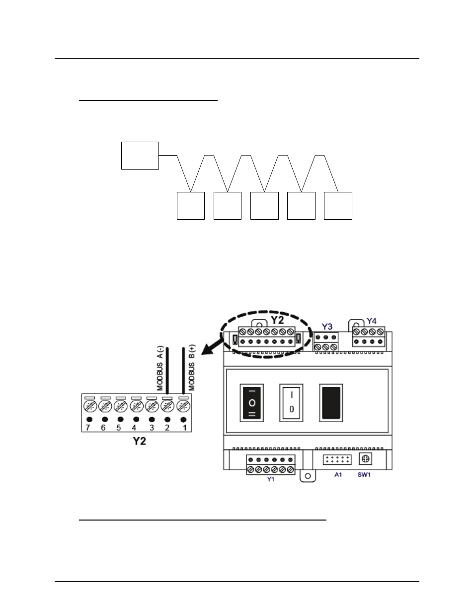
8.4.2 Physical Modbus RS485 Wiring
Modbus RS485 devices should be wired in a “Daisy-Chain” configuration similar to the example
shown Figure 8-6. DO NOT wire the units in a “Star” configuration where all devices are
connected to a central point (node).
Figure 8-6. Typical Daisy-Chain Modbus/RS485 Network
The physical wiring connections for a Modbus Network should be made using shielded twisted-
pair wire, from 18 to 24 AWG. Examples of suitable wire are: Belden # 9841, #8761, #3105A, or
equivalent.
Modbus wiring connections are made at terminals 1 and 2 of BCM connector Y2 as shown in
Figure 8-7.
Figure 8-7: BCM Modbus (RS485) Connections
8.4.3 Disconnecting the E8 from the E-Bus on the BCM Board
See Table 8-1 for how to set the three position switch on the BCM to allow disconnection of the
E8 from the BCM.
NOTE
When the BCM is configured as the primary controller, the E8 will
display the fault code “E200”.
MASTER
SLAVE
#1
SLAVE
#2
SLAVE
#3
SLAVE
#4
SLAVE
#5