Welch Allyn Duet CO2 Module - User Manual User Manual
Page 22
Duet CO
2
Module OEM Implementation Manual
Page 22
Confidential
Welch Allyn OEM Technologies
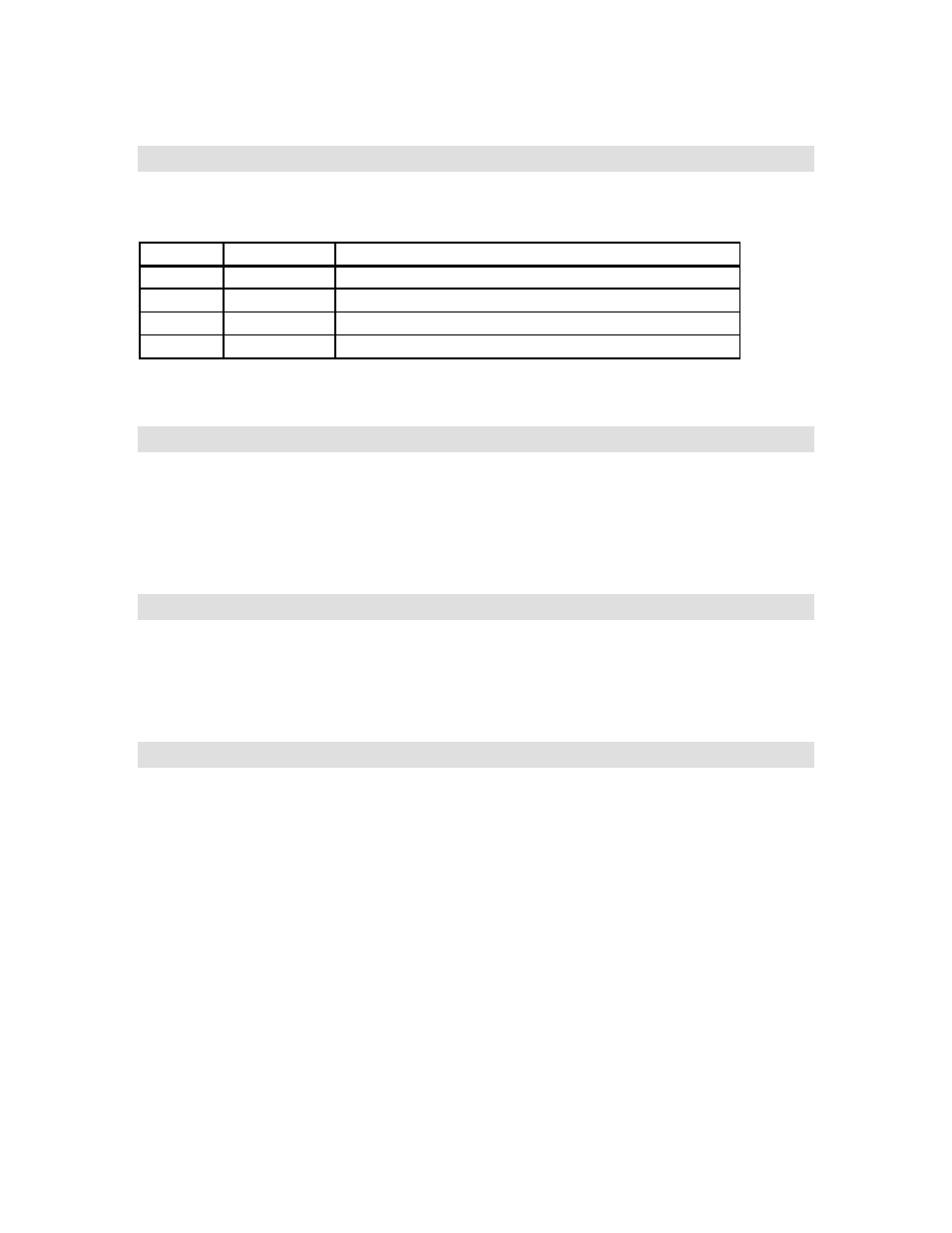
Duet Module Interface Connector
The module interface connector is a 4 pin connector (Molex p/n 22-11-2042). The host may use a 4 pin
polarized housing (Molex p/n 22-01-3047 with Molex 2759 series terminals) or equivalent.
Pin
Signal
Signal Description
1
V
in
input power
2
GND
ground
3
TxD
data from CO
2
main processor board to host system
4
RxD
data from host system to CO
2
main processor board
a.
The “square” plated through-hole designates pin 1 on the CO
2
main processor board.
Water Trap Receiver Assembly
The internal space available in the host monitor should be considered when incorporating the Water
trap receiver into the host system design. To accommodate various OEM dimensions, two water trap
receivers are offered: long and short. The long Water trap receiver requires more intrusion into the host
monitor but the Water trap does not protrude as far externally from the host chassis than with the short
Water trap receiver. The Water trap receiver assembly includes a mounted micro-switch to detect the
insertion of a Water trap.
Water Trap Switch Connection
The Water trap receiver switch is wired in the “normally open” configuration.
The Water trap switch connection is available via the connector on the sidestream daughter board. The
switch assembly is equipped with a 2-pin connector (Molex P/N 22-01-3027) which electrically
connects directly to the sidestream daughter board at P502.
Pump
The pump is mounted on the Main Processor Board. The pump wiring harness is connected to the
sidestream daughter board via a 2-pin connector (Molex P/N 22-01-3027).