Elecraft KDSP2 Manual User Manual
Page 8
8
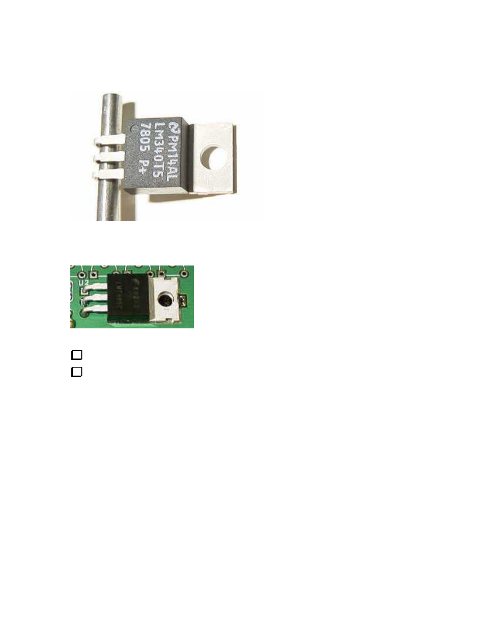
Locate U2 and match it to the PCB. Pre-bend the leads to align with the holes in the PCB while keeping
the mounting hole in U2’s tab in line with the mounting hole near the center of the PCB.
You may notice that the mounting hole area of the board near U2 has a keyhole shape isolated from the rest
of the top of the PC board, but that there are four thin traces, like the spokes of a wheel, connecting them.
This is normal - don’t cut the small traces!
You may find it helpful to use a 1/8” (0.8 mm) drill bit as a form to bend the leads of U2.
Verify the holes are aligned before you solder.
Near the center of the PCB:
U2 LM340T (LM340, 7805)
Solder the tab to the board near the end of the tab. This requires more heat than the other connections
in the board. Use a larger iron if you have one available. You do not need much solder, and DO NOT
solder near the mounting hole. The reason for soldering is to relieve mechanical stress from the leads of
U2 when the KDSP2 PCB is mounted and the mounting screw tightened
The following capacitors are ceramic monolithic with radial leads. The capacitor should sit flush to the
PCB, with exposed leads not more than about 1/32” (1mm) above the PCB.