Elecraft KDSP2 Manual User Manual
Page 5
5
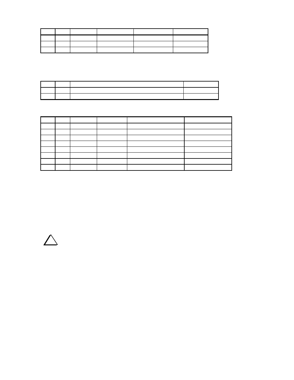
Integrated Circuits
OK Qty Reference Value
Marking
Part
Number
1 U1
ATmega8L ATMEGA8L E610015
1 U2
LM340T-5.0
LM340,
7805 E600024
1 U3
NJU6355ED
NJU6355
E600038
Note that U3 is pre-programmed with the KDSP2 application code.
Hardware
OK Qty Description
Part
Number
1
4-40x1/4” Philips pan head screw
E700005
1
4-40x0.5” Aluminum hex male-female threaded spacer
E700057
Miscellaneous
OK Qty Reference Value
Description
Part
Number
1 Y1
32.768
kHz
Crystal,
Cylindrical E660015
1
Z1
4 MHz
Ceramic Resonator, 3-pin
E660001
1
BT1
3V
CR-2032 Lithium Cell
E980039
1
DSPx
Assembled DSP Module
DSPX
1
DSP2
Printed Circuit Board
E100179
1
KDSP2 Instruction
Manual
E740050
1
1/2 x 3/8 x 2 Gray Foam
E980070
1
3/8 x3/16 x 2 Black Foam
E980069
Installing Components
Please install the parts in the order shown. After you mount a part, you may solder it in place. Double
check to be sure the part is snug against the printed circuit board (PCB). After soldering, clip the leads
close to the PCB surface.
Use a temperature-controlled soldering iron, set between 700 and 735 degrees F (370 to 390 C). Keep the
tip clean. Use rosin-core solder. Use of improper flux, or improper cleaning procedures may result in
corrosion of the soldered joint. Sometimes this takes days or weeks to appear.
i
It is important that leads be clipped close to the bottom of the PCB. Use a pair of flush-
cutting pliers, or pre-trim the leads before soldering.
As you install the following parts, check the box only after you have inspected the solder connection and
clipped the leads (unless directed to not clip the leads).