Elecraft KDSP2 Manual User Manual
Page 12
12
Near U3 is a small, cylindrical crystal. The exposed lead length should be about 0.1” (2.5 mm). Be careful
with the crystal’s leads, as they are very thin and may break if stressed. Do not attempt to push the
crystal down flush to the PC board!
Y1 32.768 kHz crystal
As long as we are on the right side of the PCB, this is a good time to install the LED. The LED is
polarized. The shorter lead goes in the square hole on the PCB. This is opposite to the rule about
electrolytic capacitors. The lead length is the only clue as to the part’s polarity, so don’t clip until you have
verified it is installed correctly!
Near the upper right-hand corner of the PCB:
LED1 Red LED (no marking)
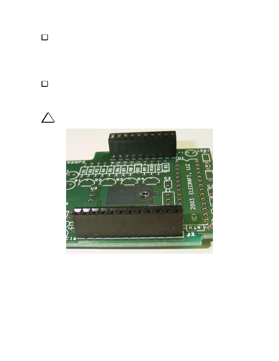
The 12-pin and 20-pin female connectors are next. These are the mating connectors for the DSPx module.
You may find it easiest to tack the connectors in place at two opposite ends, verify the connectors are
seated on the PCB and at right angles to it, then solder the remaining pins.
i
NOTE: The clearances are very tight in a K2/100, so the connectors must be flush to the
PCB.