Elecraft KDSP2 Manual User Manual
Page 6
6
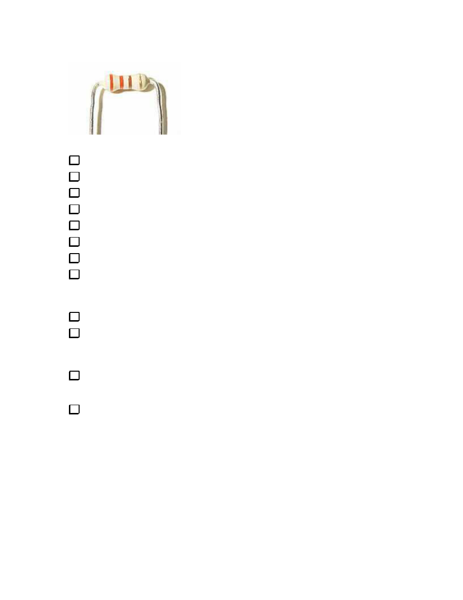
You should pre-bend the leads of resistors close to the body and at right angles. Quarter-watt resistor
locations on the PCB have 0.35” centers (9mm).
Near the upper left hand corner of the PCB:
R1 10K ohm ¼ watt 5% carbon film resistor (brown-black-orange-gold)
R2 10K ohm ¼ watt 5% carbon film resistor (brown-black-orange-gold)
R3 10K ohm ¼ watt 5% carbon film resistor (brown-black-orange-gold)
R4 10K ohm ¼ watt 5% carbon film resistor (brown-black-orange-gold)
R5 10K ohm ¼ watt 5% carbon film resistor (brown-black-orange-gold)
R6 120 ohm ¼ watt 5% carbon film resistor (brown-red-brown-gold)
R7 120 ohm ¼ watt 5% carbon film resistor (brown-red-brown-gold)
R8 120 ohm ¼ watt 5% carbon film resistor (brown-red-brown-gold)
Careful! Don’t confuse the 470 ohm and 47K ohm resistors. The color codes are very similar in
appearance.
R9 47K ohm ¼ watt 5% carbon film resistor (yellow-violet-orange-gold)
R10 10K ohm ¼ watt 5% carbon film resistor (brown-black-orange-gold)
Careful! Don’t confuse the 220 ohm and 2.2K ohm resistors. The color codes are very similar in
appearance.
R11 220 ohm ¼ watt 5% carbon film resistor (red-red-brown-gold)
Near the lower left hand corner of the PCB:
R15 2.2K ohm ¼ watt 5% carbon film resistor (red-red-red-gold)