Display (lcd) – Elecraft KX3 Owner's Manual User Manual
Page 8
8
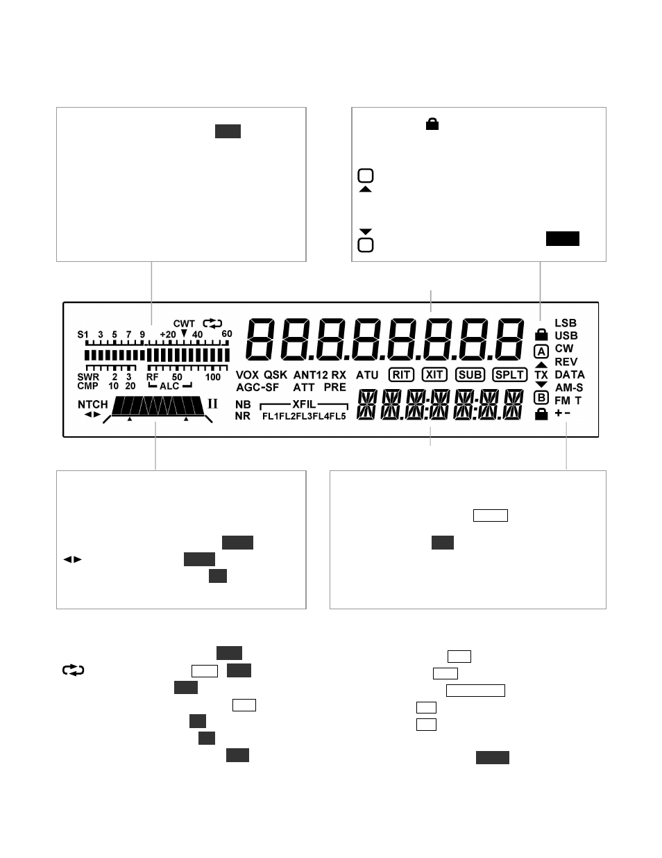
Display (LCD)
Bar graph, receive mode: Shows RX signal
strength in S-units (S-meter). If
C W T
is turned
on, the right half of the S-meter becomes a tuning
aid (pg. 13). Reducing RF gain adds a moving
reference segment (pg. 12).
Bar graph, transmit mode: Shows antenna
S W R
and
R F
output (pg. 14). In voice modes,
shows
C M P
(compression) and
A LC
(mic level)
when mic gain or CMP are set (pg. 15). ALC
scale also used to set DATA audio level (pg. 18).
VFO Icons:
Shows that a VFO or menu
entry is locked. The
TX
icon points to the transmit
VFO:
VFO A is the transmit VFO
VFO B is the transmit VFO; see
VFO A
VFO B
Filter Passband Graphic: Shows location
of receive filter passband (pg. 12)
Filter Icons:
N TC H
Auto or manual notch (
N T C H
, pg. 13)
Manual notch (
N T C H
, pg. 13)
I / II
PBT filter function (
I / I I
, pg. 12)
X FIL
Filter (
FL1
-
FL3
used, pg. 12)
Mode Icons
Basic modes (
LS B
or
U S B
,
C W
,
D A TA
,
A M
, or
FM
) are selected by tapping
M O D E
. Alternate modes
(
C W R E V
,
D A TA R E V
,
A M -S
,
FM +/-
) are
selected by holding
A L T
.
LS B
and
U S B
are alternates
of each other. In SSB mode, the
+
icon indicates
ESSB (pg. 22).
T
indicates FM PL tone (pg. 15) or
CW/DATA text decode (pg. 19).
Other Icons:
C W T
CW/data tuning aid on (
C W T
, pg. 13)
Message play/rec (
M S G
/
R E C
, pp. 16, 21)
V O X
VOX enabled (
V O X
, pp. 15, 16)
Q S K
Full break-in CW enabled (
D L Y
, pg. 16)
N B
Noise blanker on (
N B
, pg. 13)
N R
Noise reduction on (
N R
, pg. 13)
A N T
Antenna
1
/
2
, KXAT100 (
A N T
, pg. 25)
R X
Automatic RX attenuation in effect (pg. 13)
A T T
Attenuator on (
A T T
, pg. 13)
P R E
Preamp on (
P R E
, pg. 13)
A T U
ATU enabled (
A T U T U N E
, pg. 14)
R IT
RIT on (
R I T
, pg. 11)
X IT
XIT on (
X I T
, pg. 11)
S U B
Dual-watch enabled (DUAL RX, pg. 20)
S P LT
Split mode in effect (
S P L I T
, pg. 19)
TX
A
TX
B
SPLIT