Calibration, Reference frequency – Elecraft KX3 Owner's Manual User Manual
Page 31
31
Calibration
Most calibration steps are performed at the
factory for both kit and assembled KX3s.
There is one exception: If you install a KXFL3
roofing filter after initial purchase, you’ll need to
perform the Receive Sideband calibration step
(pg 32).
Viewing tech-mode menu entries: To view the
menu entries used during calibration, hold
M E N U
,
then rotate
O F S / V F O B
to locate the TECH
MD menu entry. Use VFO A to change the
parameter to
O N
.
To unlock the parameter for a tech-mode menu
entry: Hold
K H Z
until you see the lock symbol
( ) turn off (about 3 seconds).
Reference Frequency
Using the calibration procedure below, you can
achieve accuracy of better than +/- 1 ppm. This
procedure requires a stable signal generator, or an
on-air signal at a known frequency, such as WWV
at 5, 10, or 15 MHz. The carrier of a commercial
AM broadcast station can also be used.
If better frequency stability is desired, refer to
the Extended VFO Temperature Compensation
procedure, available on our KX3 web page.
During the procedure, you’ll have a choice of
two methods for adjusting the reference frequency:
(1) automatic tuning, or (2) manual tuning.
Method (2) may be slightly more accurate but
requires “zero-beating” of two signals, which some
operators may find difficult to do.
§
Select CW mode by tapping
M O D E
.
§
Hold
M E N U
. Rotate
O F S / V F O B
to find
DUAL RX. Set it to
O FF
, then exit the menu.
§
If you’re using a signal generator, set
P W R
to 0.0 watts to avoid damaging it.
§
Use direct frequency entry (pg. 10) to set VFO
A to the exact frequency of your signal
generator or on-air signal source. This will also
switch the KX3 to the required band.
§
Set AF gain for a comfortable listening level.
You should be able to hear a carrier.
§
Method 1 (automatic tuning): Hold
C W T
.
The upper half of the S-meter becomes a tuning
aid, with the
C W T
icon turned on. This enables
the auto-spot function to be used below.
Method 2 (manual tuning): This method
requires manually matching the pitch of the
received signal to the CW sidetone pitch using
S P O T
. To prepare for this, you may need to
increase sidetone volume. See pg. 12.
§
Locate the I/II icons (right end of the filter
passband graphic). If function II is selected, tap
P B T I / I I
to select function I (bandwidth).
§
Rotate the
P B T I / I I
control to set the
bandwidth to 0.30 kHz (
B W 0.30
).
§
Tap
P B T I / I I
to switch to function II (shift).
§
Rotate the
P B T I / I I
control until the filter
passband is centered in the filter graphic.
§
Hold
M E N U
, then rotate
O F S / V F O B
to
locate the REF CAL menu entry.
§
Hold
K H Z
for about 3 seconds to unlock the
parameter (shown on VFO A).
§
If you see only 7 digits, tap
R A T E
.
§
In case you decide to restore the factory setting,
write down the full 8-digit parameter value:
_________________ .
§
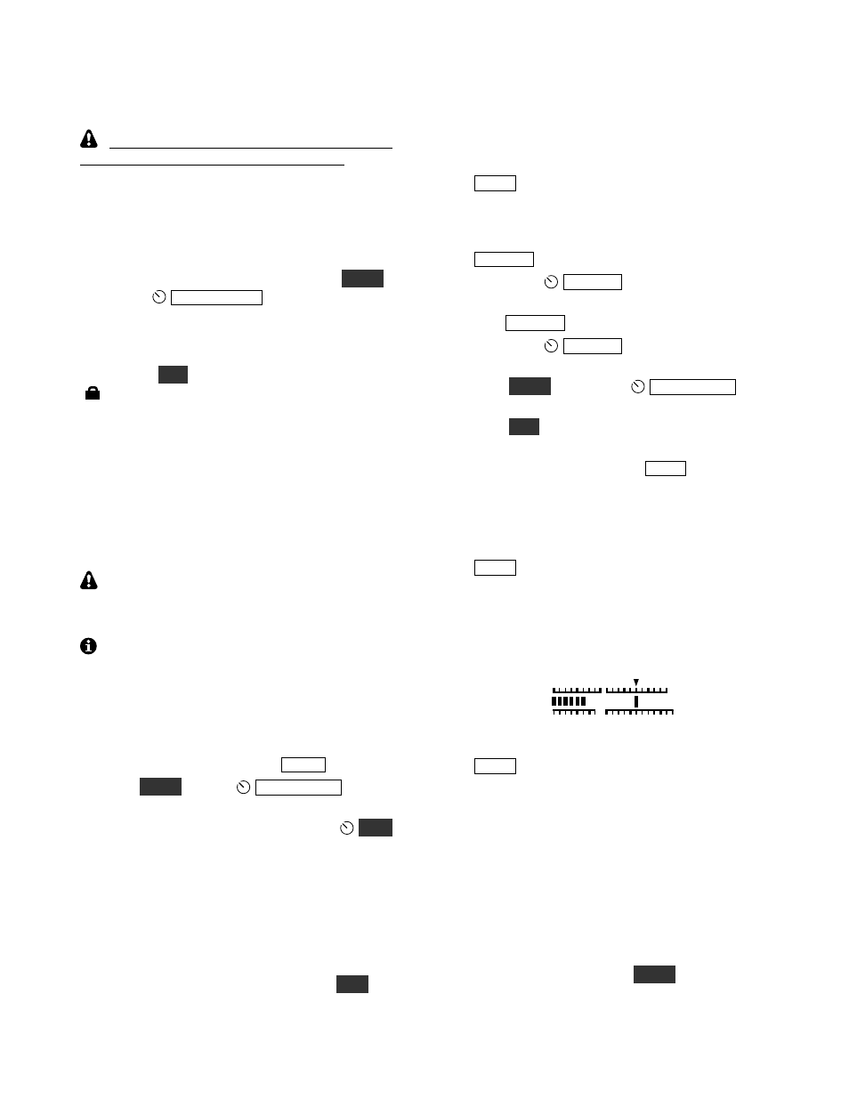
Method 1 (automatic tuning, CWT on): Tap
S P O T
to auto-spot the signal. The REF CAL
parameter value should automatically move up
or down a small amount. When it finishes
moving, the bar directly beneath the
C W T
icon
should be turned on as shown below. The
reference will then be closely calibrated.
Method 2 (manual tuning, CWT off): Tap
S P O T
and manually adjust the REF CAL
parameter using VFO A until the received
signal pitch matches the sidetone pitch. Adjust
for zero-beat.
§
If you have difficulty with this procedure, or if
you’re not sure that it worked correctly, set the
parameter value to its original value (recorded
above) using VFO A.
§
If you have adjusted the REF CAL value more
accurately, write down the new value (8 digits)
here for future reference: ______________ .
§
Exit the menu by holding
M E N U
.
§
Save your configuration using KX3 Utility.
50
100
2 3
SWR
RF
CWT
S1 3 5 7 9