7 sensor and relay pinhole allocation on nx8000, 2 i/o card sensor and relay pinhole allocation, Sensor and relay pinhole allocation on nx8000 – AVer NX8000 User Manual
Page 15: Connecting the sensor/relay device to i/o card, I/o card sensor and relay pinhole allocation
8
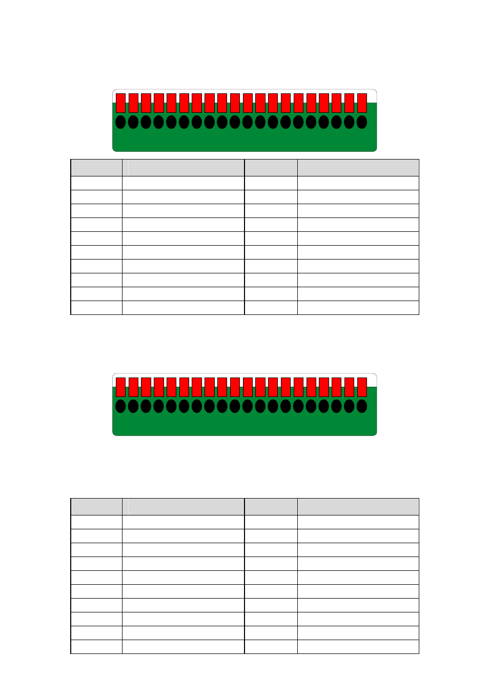
2.7 Sensor and Relay pinhole allocation on NX8000
The signal from the sensor (i.e., infrared sensors, smoke detectors, proximity sensors, door
sensors, etc.) is being transmitted to the I/O card, and this triggers the system to respond and
send signal to relay device (i.e., alarm, telephone etc).
20
19
18
17
16
15
14
13
12
11
10
9
8
7
6
5
4
3
2
1
Pin #
Definition
Pin #
Definition
1
Sensor input signal 1+
11
Relay Normal Close 1
2
Sensor output signal 1-(GND)
12
Relay Common 2
3
Sensor input signal 2+
13
Relay Normal Open 2
4
Sensor output signal 2-(GND)
14
Relay Normal Close 2
5
Sensor input signal 3+
15
Relay Common 3
6
Sensor output signal 3-(GND)
16
Relay Normal Open 3
7
Sensor input signal 4+
17
Relay Normal Close 3
8
Sensor output signal 4-(GND)
18
Relay Common 4
9
Relay Common 1
19
Relay Normal Open 4
10
Relay Normal Open 1
20
Relay Normal Close 4
2.7.1
Connecting the Sensor/Relay device to I/O card
The I/O Audio card enables you to connect (4) sensor inputs and (4) relay outputs. Just
connect the external sensor and relay pin directly to the pinhole on the NX8000 card. Check
the table below and locate which pinhole is assigned to sensor input and relay output.
20
19
18
17
16
15
14
13
12
11
10
9
8
7
6
5
4
3
2
1
2.7.2 I/O Card Sensor and Relay pinhole allocation:
The signal from the sensor (i.e., infrared sensors, smoke detectors, proximity sensors, door
sensors, etc.) is being transmitted to the I/O card and this triggers the system to respond and
send signal to relay device (i.e., alarm, telephone etc).
Pin #
Definition
Pin #
Definition
1
Sensor input signal 1+
11
Relay Normal Close 1
2
Sensor output signal 1-(GND)
12
Relay Common 2
3
Sensor input signal 2+
13
Relay Normal Open 2
4
Sensor output signal 2-(GND)
14
Relay Normal Close 2
5
Sensor input signal 3+
15
Relay Common 3
6
Sensor output signal 3-(GND)
16
Relay Normal Open 3
7
Sensor input signal 4+
17
Relay Normal Close 3
8
Sensor output signal 4-(GND)
18
Relay Common 4
9
Relay Common 1
19
Relay Normal Open 4
10
Relay Normal Open 1
20
Relay Normal Close 4