Table 3.5 – Wheatheart Swing Away Flex Auger User Manual
Page 72
3. A
SSEMBLY
W
HEATHEART
- SA F
LEX
A
UGER
3.16. F
LEX
A
UGER
H
YDRAULICS
71’ - 111’
72
30651 R5
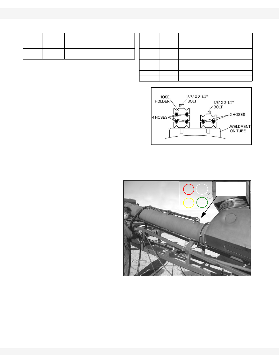
2. Loosely
connect
hydraulic hose
holders to swing and flex tubes.
Note that only two hose holders
are required at the top end of the
flex tube (Figure 3.70). Three
hose holders stacked together
can hold four hoses, two hose
holders stacked together can
hold two hoses. Refer to Figure
3.62.
• Three hose holders attach to
weldments with 3/8” x 3-1/2” bolts and locknuts.
• Two hose holders attach to weldments on tubes with 3/8” x 2-1/4” bolts
and locknuts.
3. Loosely
connect
hydraulic hose
holders to hold four
hoses (see left side of
Figure 3.62) to
brackets on side of
flex frame as shown
in Figure 3.63.
4. Use hose bundle
marked with part
number 29207
(contains four hoses)
and secure to flex
tube as shown in
Figure 3.63 with hose
holders.
8
28835
3/8" X 78" HYDRAULIC HOSE, MK FLEX
H
28761
STEEL ELBOW 90, 8MJIC X 8FJIC
29206
UPPER HOSE ASSEM, MK FLEX
J
28759
STEEL ELBOW 90, 10MORB X 8MJIC
29207
LOWER HOSE ASSEM, MK FLEX
K
28504
STEEL ELBOW 45, 6MORB X 6MJIC
L
28478
STEEL ELBOW 1/2MNPT X 1/2 FNPSM
M
28508
STEEL,8MORBX1/2FNPSMX1/16 ORIFICE
N
28654
#8 M-ORB-1/2F-NPT-90DEG FITTING
O
29087
STEEL ELBOW 90, 12MNPT X 8FNPSM
Table 3.5
LABEL
PART NO.
DESCRIPTION
LABEL
PART
NO.
DESCRIPTION
Figure 3.62
Figure 3.63
ASSEMBLE HOSES
HERE, REFERRING
TO CIRCLES FOR
COLOUR
RED
WHITE
YELLOW GREEN