Hydraulics (71’–91’), Cylinder installation, Lift cylinder (figure 3.37). if lift cabl – Wheatheart Swing Away Flex Auger User Manual
Page 54: Shown in figure 3.37. make cert, Shown in figure 3.37, Ch bracket as shown in figure 3.37
3. A
SSEMBLY
W
HEATHEART
- SA F
LEX
A
UGER
3.13. H
YDRAULICS
(71’–91’)
71’ - 111’
54
30651 R5
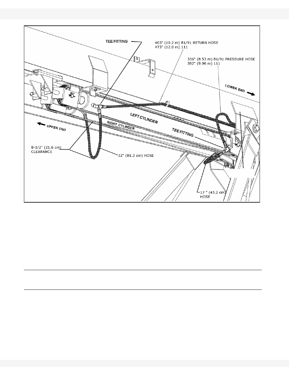
Figure 3.37
11. Place both hoses into retaining brackets welded to side of auger tube and
boot. Bend tops of brackets over slightly to hold hoses in place.
Important:
Protect hose ends from dirt.
12. Recheck that bolts on undercarriage, lift cylinders, and cable clamps are
tight, then remove auger tube support.
3.13. HYDRAULICS (71’–91’)
3.13.1. C
YLINDER
I
NSTALLATION
Note:
See Table 3.3 for the appropriate cylinders.
1. The
transport
brace (item 34 from Figure 3.24) must be installed and
supporting the frame.
2. Position
the
cylinders (1) on the cylinder lugs (2). The rod end of the
cylinders must be attached to the lower cylinder mount so that the rod
extends towards the intake (Figure 3.38).
Note:
The ports need to be facing each other, see Figure 3.39.
BACK ARM
BRACKET