Flex auger boot – Wheatheart Swing Away Flex Auger User Manual
Page 27
W
HEATHEART
- SA F
LEX
A
UGER
3. A
SSEMBLY
71’ - 111’
3.3. F
LEX
A
UGER
B
OOT
30651 R5
27
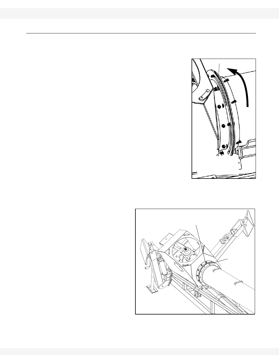
3.3. FLEX AUGER BOOT
.
Complete assembly in the order listed to prevent premature failure of the lower
bearing. Refer to Figure 3.8 to 3.10.
1. Attach boot spinner plates.
a. Insert plates between boot spinner and
upper flex tube bundle.
b. Mount onto the four 7/16” x 1-3/4” bolts
welded to the tube.
c. Fasten with 7/16” locknuts and 7/16”
washers.
d. Do not tighten all the way.
e. Ensure boot is angled on the same side as
swing tube is to be installed.
f. Secure with eight 7/16” x 1-1/4” bolts with
locknuts and washer.
Flex boot can be rotated to the left or the right side
of the auger. Figure 3.9 and 3.10 show setup for
swing on right side of the auger, as viewed from
the intake end facing toward the spout. To install
the flex boot on left side, rotate boot to left side
2. Place 1-3/4” wide rim washer and 1-3/4”
bearing and flange on flight shaft with 5/8” x 1-3/4” bolts and locknuts. Do not
tighten until Step 5.
Grease zerk should be
located on left side of
bearing.
3. Install
square key and
slide lower sprocket onto
flight shaft.
4. Align lower sprocket with
upper sprocket using
straight edge, then
tighten set screws.
5. Install roller chain on
sprockets and adjust
tension to about 1/4”
(0.64 cm) deflection.
Tighten the 4 bolts on
lower bearing and
secure lock collar. Oil
chain lightly.
Figure 3.8
ROTATE FLEX BOOT
AS SHOWN BY
ARROW FOR LEFT
SIDE USE
BOOT SPINNER PLATE
Note:
7/16” X 1-1/4”
BOLTS
7/16” WASHERS & LOCKNUTS
Figure 3.9
Important: