Adjustable towbar, Notice – Wheatheart Swing Away Flex Auger User Manual
Page 30
3. A
SSEMBLY
W
HEATHEART
- SA F
LEX
A
UGER
3.5. A
DJUSTABLE
T
OWBAR
71’ - 111’
30
30651 R5
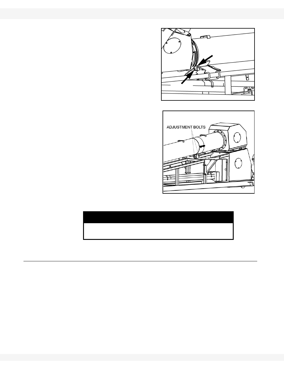
5. Adjust
the
position of the flex tube
support, so that the lock pin sticks
through the transport latch approxi-
mately 1/16” (1.6 mm). Tighten u-
bolts and locknuts and secure. See
Figure 3.12.
6. Use a hoist to lift the lower end of
flex tube slightly and adjust the
position of the pivot roller with the
1/2” x 2-1/2” adjustment bolts to
carry the weight of the flex tube. See
Figure 3.13.
3.5. ADJUSTABLE TOWBAR
The Flex has an adjustable towbar. The towbar is installed as seen in Figure
3.14.
1. Insert the adjustable towbar into the boot channel. Secure by placing a 3/4” x
6-1/2” long bolt and locknut through the back hole in the boot channel, under
the flex frame.
2. Insert a 5/8” x 4-1/2” long bolt and locknut vertically into the hole at the front
of the boot so that the towbar comes straight out from the flex frame.
• This bolt must be inserted from the bottom with the nut on top.
Important:
Adjust the towbar if a speed-reducing gearbox is used with the system. In this
case, the towbar is extended and pinned on an angle using the vertical bolt. This
will line up the PTO with the PTO connection on the gearbox.
NOTICE
Failure to lift the flex tube when adjusting the pivot roller can
result in damage to the roller and/or flex tube.
Figure 3.12
LOCK PIN
TRANSPORT
LATCH
Figure 3.13