Wheatheart Swing Away Flex Auger User Manual
Page 25
W
HEATHEART
- SA F
LEX
A
UGER
3. A
SSEMBLY
71’ - 111’
3.1. T
UBES
& F
LIGHTING
30651 R5
25
21. Place bracket under middle of driveline with spacer and use shims provided
to level.
22. To install chain coupler (shipped assembled):
a. On the two half-sprockets: check to make sure the keyways are NOT lined
up. If they are, disassemble the chain coupler and offset the keyways, then
reassemble.
b. Slide the chain coupler onto the lower flight stub shaft, and attach it using
3/8” x 2-1/2” roll pin.
c. Install the 3/8” x 1-3/4” square key onto the solid driveshaft, and slide the
driveshaft into the opposite end of the chain coupler. Slide it in 1-3/4”, until
the end of the driveshaft is flush with the end of the sprocket.
d. Secure both sides of the chain coupler using the setscrews; tighten
securely.
e. Disassemble the 1-3/4” wooden bearing (as supplied). Re-assemble the
bearing around the solid driveshaft, and attach it to the frame using two
3/8” x 2-1/4” bolts and locknuts provided. Use shims as necessary; wood
bearing is there for support only, DO NOT force shims into place. Once
satisfied with driveline alignment, tighten bolts and locknuts securely.
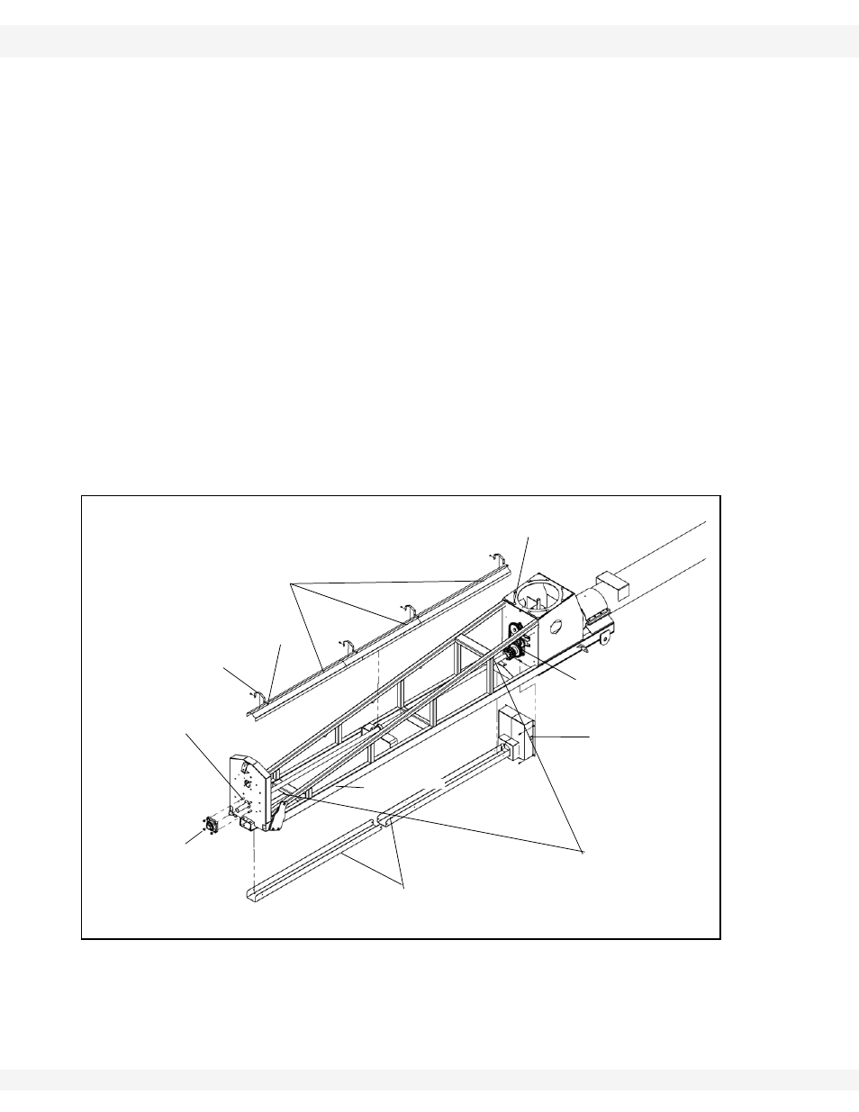
Figure 3.6
23. Secure the driveshaft to the front plate of the flex frame with a 1-3/4” bearing
and flange and four 5/8” x 1-3/4” bolts and locknuts. Secure lower driveshaft
with locking collar and setscrew.
24. Grease zerk should be located on left side of bearing.
SPROCKET
COVER
FLEX FRAME
SMS #14 X 5/8”
WITH
WASHERHEAD
DRIVESHAFT
SHIELD
STRAP
DRIVESHAFT
SHIELDS
5/8” LOCKNUTS
LOWER
DRIVESHAFT
GUARD
5/8” X 1-3/4”
BOLTS
FLEX FRAME
BOOT
LOWER
FLIGHT SHAFT
3/8” X1” CARRIAGE
BOLTS