Discharge spout & thrust adjuster – Wheatheart Swing Away Flex Auger User Manual
Page 31
W
HEATHEART
- SA F
LEX
A
UGER
3. A
SSEMBLY
71’ - 111’
3.6. D
ISCHARGE
S
POUT
& T
HRUST
A
DJUSTER
30651 R5
31
3. Install the PTO cradle bracket on the front plate of the flex frame. Attach
bracket with two 7/16” x 1-1/4” bolts and locknuts.
Figure 3.14
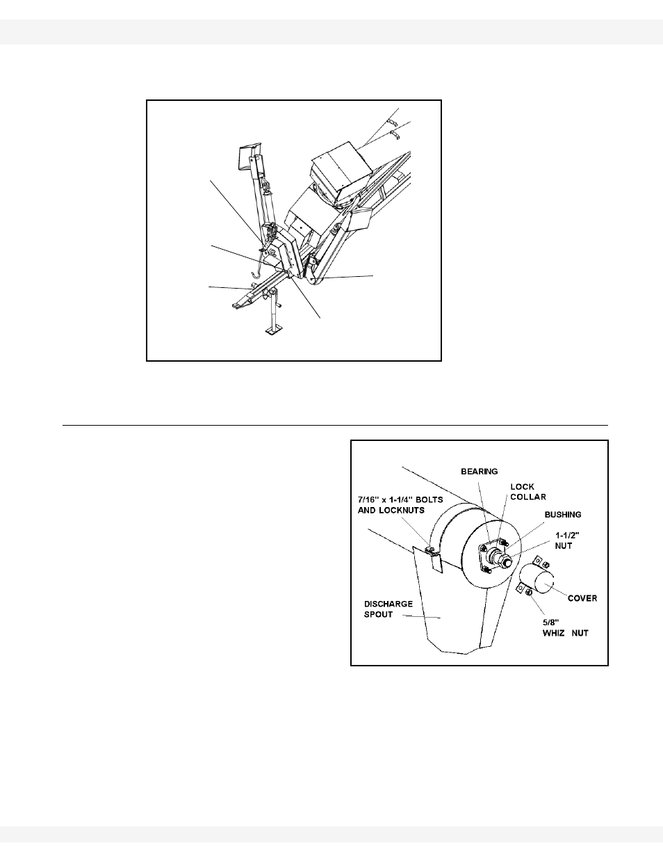
3.6. DISCHARGE SPOUT & THRUST ADJUSTER
• Attach discharge spout with
7/16” x 1-1/4” bolts and lock-
nuts.
• The thrust adjuster is designed
to transfer some pressure from
the lower flight bearing to the
upper flight bearing.
• Remove cover and 5/8”
whiz nuts.
• Loosen the set screw on
the lock collar and disen-
gage the lock collar from
the bearing to allow free
movement of the flight
shaft.
• Turn the 1-1/2” nut until it is snug against the bushing, then turn it so that
the flight shaft moves an additional 1/4” (0.64 cm).
• Secure the lock collar and tighten the set screw.
• Re-install the cover over the two longer 5/8” bolts. Secure with two 5/8”
whiz nuts.
ADJUSTABLE
TOWBAR
BOOT CHANNEL
3/4” X 6-1/2”
BOLT &
LOCKNUT
5/8” X 4-1/2”
BOLT &
LOCKNUT
PTO CRADLE
BRACKET