Is point! (figure 3.4) – Wheatheart Swing Away Flex Auger User Manual
Page 23
W
HEATHEART
- SA F
LEX
A
UGER
3. A
SSEMBLY
71’ - 111’
3.1. T
UBES
& F
LIGHTING
30651 R5
23
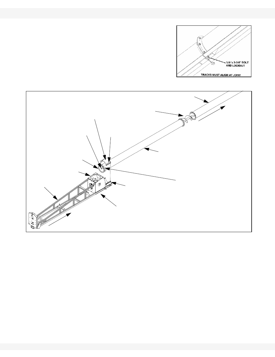
5. 111’ only: Bolt the track ends together
6. Adjust lower auger tube out until it is flush
with the flight shaft end (see Figure 3.4).
7. Lift the flex frame up underneath the lower
tube and secure on benches.
8. Push the flex frame toward the spout to
slide the auger flight through the front of the
flex frame boot.
Figure 3.4
9. Connect flex frame assembly to lower auger tube flange with twelve 7/16” x
1-1/4” GR8 bolts and locknuts.
10. Secure tube support clamp to tube with eight 5/8” x 2-1/4” GR8 bolts and
locknuts.
Important:
Steps 11. to 19. must be completed in the order listed to prevent premature
failure of the lower bearing. Refer to Figure 3.5.
11. Slide lower bearing onto flight stub and secure boot loosely with four 5/8” x
1-3/4” bolts and 5/8” locknuts.
12. Loosen setscrew on lock collar and slide it onto the lower flight. Leave lock
collar loose for now.
Important:
Grease zerk should be located on left side of bearing.
13. Seat flight shaft shoulder against washer and lower bearing, see Figure 3.5.
Do not tighten bearing bolts until after Step 18.
Figure 3.3 111’ only
ALIGN END OF TUBE WITH
END OF FLIGHT SHAFT.
LIFT FLEX FRAME UP
INTO PLACE.
SLIDE BACK SO TUBES
CONTACT ONE ANOTHER.
FLEX
FRAME
FLEX
FRAME
BOOT
5/8” X 2-1/4”
BOLTS
5/8” LOCKNUTS
LOWER
AUGER
TUBE
MID-AUGER
TUBE
FLIGHT SHAFT
END
AUGER FLIGHT
TUBE SUPPORT
CLAMP
SP
OU
T
7/16” X 1-1/4”
GR8 BOLTS
NOTE: Tubes may not be
exactly as illustrated.