Flex frame components – Wheatheart Swing Away Flex Auger User Manual
Page 26
3. A
SSEMBLY
W
HEATHEART
- SA F
LEX
A
UGER
3.2. F
LEX
F
RAME
C
OMPONENTS
71’ - 111’
26
30651 R5
25. Attach sprocket covers to flex frame boot with four 5/16” x 3/4” bolts and
locknuts.
26. Place two 60” and one 48” driveline guards over shaft and secure to flex
frame with driveshaft shield straps and SMS #14 x 5/8” with washerhead.
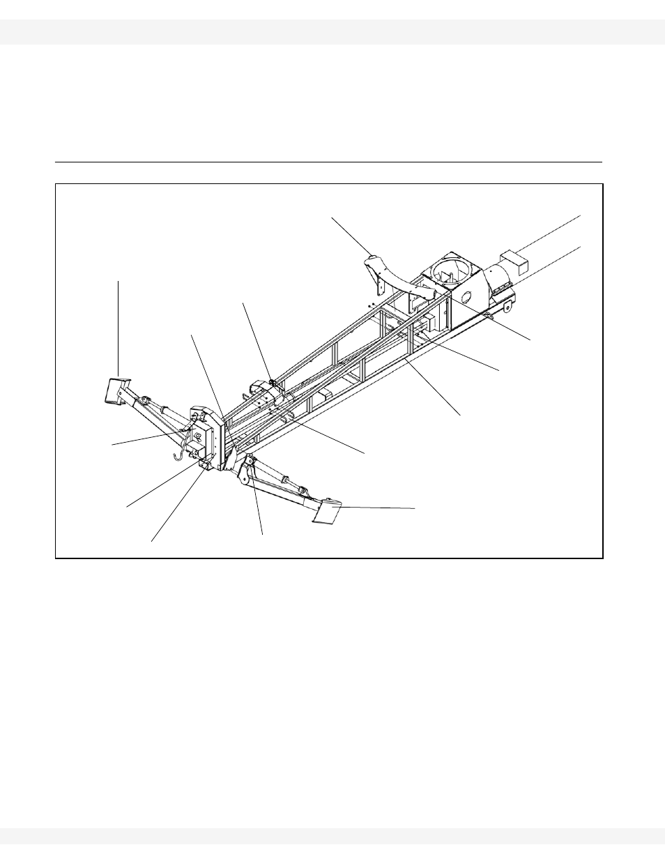
3.2. FLEX FRAME COMPONENTS
Figure 3.7
1. Install
outrigger
legs. Insert 1/2” x 1-1/2” carriage bolts pointing inward to
prevent interference with hydraulic cylinder.
Important:
There is a left and a right outrigger leg. Ensure they are installed with ports facing
the discharge.
2. Place roller support inside key stops on flex frame, see Figure 3.7. The four
1/2” x 2” x 3-3/4” u-bolts are attached around the upright tubes, as shown in
Figure 3.7. Ensure that these u-bolts are tightened securely.
3. Install sprocket guard on boot with four 5/16” x 3/4” bolts. Ensure that tabs on
2 piece sprocket guard are fit into the slots on either side of the lower guard.
Tighten the top half of the lower guard.
4. Attach the transport rest to flex frame with four 1/2” X 2” x 3-1/4 u-bolts and
locknuts. Leave flex tube support transfer rest untightened until after the flex
tube is installed.
1/2” X 2” X 3-1/4”
U-BOLT
LEFT OUTRIGGER LEG
1/2” X 1-1/2”
CARRIAGE BOLT
5/16” LOCKNUT
RIGHT OUTRIGGER LEG
SPROCKET
GUARD
5/16” X 3/4”
BOLT
5/16” X 3/4”
BOLT
ROLLER SUPPORT
TRANSPORT REST
1/2” LOCKNUT
1/2” LOCKNUT
1/2” X 2” X 3-1/4” U-BOLT