Must b, Ng. refer to figure 3.5, See figure 3.5 – Wheatheart Swing Away Flex Auger User Manual
Page 24: Ep 18
3. A
SSEMBLY
W
HEATHEART
- SA F
LEX
A
UGER
3.1. T
UBES
& F
LIGHTING
71’ - 111’
24
30651 R5
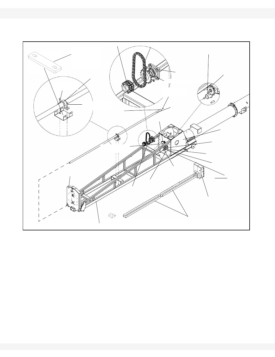
14. Now, slide the middle and lower tube sections together and secure with
twelve 7/16” x 1-1/4” bolts and locknuts.
Figure 3.5
15. Install 3/8” x 3-1/2” square key and slide lower sprocket onto lower flight
shaft.
16. Align upper sprocket with lower sprocket and chain tensioner sprocket using
straight edge, then tighten setscrews and locking collar on upper bearing.
17. Loosen chain tightener sprocket and install roller chain on upper and lower
sprockets. Secure with connecting link and clip.
18. Oil chain lightly and tension.
19. Tighten 5/8” locknuts on the lower bearing. Tighten collar on lower bearing
and tighten setscrew.
20. Install two sections of lower driveshaft guard as well ad the driveshaft guard
extension with 3/8” x 1” carriage bolts and 3/8” x 1” bolts and flange nuts.
Tighten the guard extension and lower half of the guard. Leave the top half
hand tight until the two piece chain guard is in place. Figure 3.5.
Note:
The driveshaft ends are different. Make sure the end with the hole is at the lower
end of the flex frame.
3/8” X 2-1/2”
ROLL PIN
FLEX FRAME
BOOT
LOWER
FLIGHT SHAFT
FLEX FRAME
UPPER
DRIVESHAFT
5/8”
LOCKNUTS
WIDE RIM FLAT
WASHER
3/8” - 3-1/2”
SQUARE KEY
ROLLER
CHAIN
CHAIN
TIGHTENER
CHAIN
TIGHTENER
SPROCKET
5/8” X 1-3/4”
BOLTS
NOTE: GREASE
ZERK TO LEFT
SIDE
3/8” X 2-1/2” ROLL PIN
THROUGH THIS HOLE IN
LOWER FLIGHT STUB SHAFT
ADD SHIMS AS
REQUIRED TO
LEVEL
DRIVESHAFT
CHAIN COUPLER
ROLLER CHAIN
5/8” LOCKNUT
1-3/4” WOODEN
BEARING
3/8” X 2-1/4”
BOLT
LOWER BEARING
UPPER BEARING
& SPROCKET
END PLATE
3/8” X 2-1/4”
BOLT
3/8” X 1-3/4”
SQUARE KEY
LOWER DRIVESHAFT
GUARD
SPROCKET COVER