Connecting flex tube to flex frame – Wheatheart Swing Away Flex Auger User Manual
Page 29
W
HEATHEART
- SA F
LEX
A
UGER
3. A
SSEMBLY
71’ - 111’
3.4. C
ONNECTING
F
LEX
T
UBE
TO
F
LEX
F
RAME
30651 R5
29
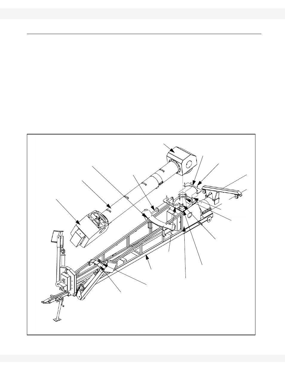
3.4. CONNECTING FLEX TUBE TO FLEX FRAME
1. Place wide rim flat washer and 1/4” x 1-1/4” key on the gearbox shaft.
2. Place upper flex tube on flex frame as shown aligning u-joint in flex tube
spout on the gearbox in the boot.
3. Place 6 galvanized spacers (4 in front, 2 in back) and 2 pivot plates on flex
frame boot. Secure flex spout on flex frame with 7/16” x 1-3/4”
bolts and
locknuts.
• Upper plate has grease nipples on it; the lower plate does not.
• Grease nipples are in bolt bag and need to be installed.
Important:
Pivot plates must be installed as illustrated.
4. Install 2-1/2” x 16” cylinder to flex spout and cylinder bracket as shown in
Figure 3.11. Use two 1/4” x 1-3/4” cotter pins to assemble cylinder pin and
use snap rings provided to assemble clevis pin.
Figure 3.11
FLEX TUBE
HYDRAULIC
CYLINDER
2-1/2” X 16”
UPPER PIVOT PLATE
WITH GREASE FITTINGS
7/16” X 1-3/4”
BOLT AND 7/16”
FLAT WASHER
LOWER PIVOT
PLATE
FOUR GALVANIZED
SPACERS
FLEX FRAME
FLEX TUBE SUPPORT
FLEX TUBE
BOOT
CYLINDER
BRACKET
FLEX SPOUT
GEARBOX SHAFT
WIDE RIM FLAT WASHER,
AND 1/4” X 1-1/4” KEY
FLEX FRAME
BOOT
SPRING PIN
7/16” LOCKNUT
TWO
GALVANIZED
SPACERS