Module installation and configuration, Module configuration rules, Jççìäé=fåëí~дд~нбзе=~ез=`зесбцмк~нбзе – Barco DX-700 User Manual
Page 55: Jççìäé=`зесбцмк~нбзе=oìäéë, Hardware orientation
DX-700 • User’s Guide • Rev 02
55
2. Hardware Orientation
Module Installation and Configuration
jçÇìäÉ=fåëí~дд~нбзе=~еЗ=`зеСбЦмк~нбзе
The following topics are discussed in this section:
•
•
Module Insertion and Extraction
•
jçÇìäÉ=`зеСбЦмк~нбзе=oìäÉë
DX-700 input and output modules can be configured in a variety of ways, but important sets
of rules apply to their placement. As a prerequisite, ensure that you are familiar with the
“
” section, on page 24 in Chapter 1.
Please note the following important “module” rules:
•
In the most basic of DX-700 “single bank” configurations, you must have at least
one input module and one output module — to route video to an LED wall.
•
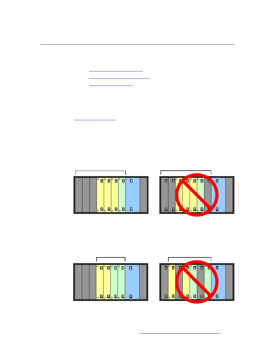
As you face the rear of the chassis, the right-most module within the entire Input /
Output Section
must always be an Output Module, and it must always be right-
justified against the System Module.
Figure 2-12.
Right justification of Output Modules against the System Module
•
Within any bank, all modules must be adjacent to each other — with no blank
panels in-between, and all Output Module(s) are always right-justified.
Figure 2-13.
Adjacent modules within a bank
Blank
Blank
Blank
Input
Input
Input
O
u
tput
Sy
s
tem
Powe
r
Inpu
t
Inpu
t
Inpu
t
Ou
tpu
t
Sy
s
te
m
Po
wer
Bl
ank
Bl
ank
Bl
ank
Correct Justification
Incorrect Justification
Input / Output Section
Input / Output Section
Blank
Input
O
u
tput
Sy
s
tem
Powe
r
Input
O
u
tput
Blank
Blank
Correct Justification
Incorrect Justification
Inpu
t
Ou
tpu
t
Sy
s
te
m
Po
wer
Ou
tpu
t
Inpu
t
Bl
ank
Bl
ank
Bl
ank
Bank 1
Bank 1