Standard dvi-i connector, K==pééåáñáå~нбзел, Pн~ез~кз=asfjf=`зеейензк – Barco DX-700 User Manual
Page 181
DX-700 • User’s Guide • Rev 02
181
^K==péÉÅáÑáÅ~нбзел
Pinouts
pн~еЗ~кЗ=asfJf=`зееЙЕнзк
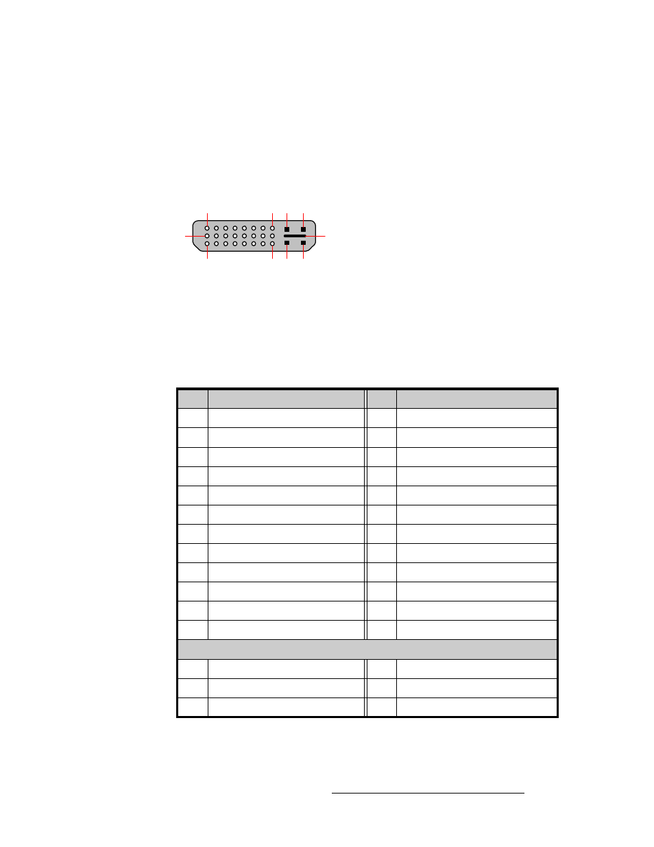
The figure below illustrates the standard DVI-I connector, which is used for the following
connections:
•
Input Module: EXP OUT connector
•
Input Module: DVI / EXP IN connector
•
System Module: DVI Monitor Output connector
Figure A-2.
Standard DVI-I connector
The table below lists standard DVI-I connector pinouts. Please note:
•
T.M.D.S = Transition Minimized Differential Signal
•
DDC = Display Data Channel
Table A-4.
Standard DVI-I Connector Pinouts
Pin
Signal
Pin
Signal
1
T.M.D.S. Data 2-
13
T.M.D.S. Data 3+
2
T.M.D.S. Data 2+
14
+5V Power
3
T.M.D.S. Data 2/4 Shield
15
ground (for +5V)
4
T.M.D.S. Data 4-
16
Hot Plug Detect
5
T.M.D.S. Data 4+
17
T.M.D.S. Data 0-
6
DDC Clock
18
T.M.D.S. Data 0+
7
DDC Data
19
T.M.D.S. Data 0/5 Shield
8
Analog Vertical Sync
20
T.M.D.S. Data 5-
9
T.M.D.S. Data 1-
21
T.M.D.S. Data 5+
10
T.M.D.S. Data 1+
22
T.M.D.S. Clock Shield
11
T.M.D.S. Data 1/3 Shield
23
T.M.D.S. Clock +
12
T.M.D.S. Data 3-
24
T.M.D.S. Clock -
MicroCross Pins
C1
Analog Red Video
C4
Analog Horizontal Sync
C2
Analog Green Video
C5
Analog Common Ground Return
C3
Analog Blue Video
1
8
9
17
24
C1 C2
C3 C4
C5