Connectivity diagrams, Single bank, single input source, single output, Зеейенбобну=aб~цк~гл – Barco DX-700 User Manual
Page 30: Páåöäé=_~åâi=páåöäé=fåéìí=pçìêåéi=páåöäé=lìíéìí, Nk==fåíêççìåíáçå
30
DX-700 • User’s Guide • Rev 02
NK==fåíêçÇìÅíáçå
Connectivity Diagrams
`зееЙЕнбобну=aб~Цк~гл
This section provides several sample “single bank” connectivity diagrams.
•
Single Bank, Single Input Source, Single Output
•
Single Bank, Triple Input Sources, Ungrouped Output
•
Single Bank, Single Input Source, Grouped Output
páåÖäÉ=_~åâI=páåÖäÉ=fåéìí=pçìêÅÉI=páåÖäÉ=lìíéìí
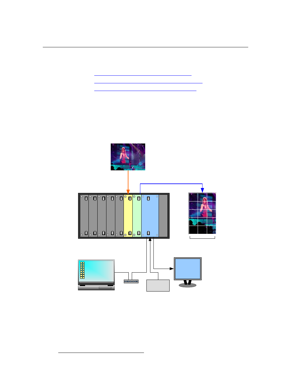
The figure below illustrates a sample DX-700 “single bank” configuration. In this
configuration, the bank consists of a single input module and a single output module. One
input source is mapped to one of the output module’s three output connectors, and is used
to drive a single video wall.
Figure 1-7. Sample system configuration: single input, single output
Blan
k Pa
ne
l
Blan
k Pa
ne
l
Blan
k Pa
ne
l
O
u
tp
ut
Mo
du
le
Sy
s
te
m
Mo
d
u
le
Po
wer
Su
p
p
ly
Inp
u
t Mo
du
le
Source 1
LED Wall 1
OLite
Sync
Generator
Laptop PC
(Director Toolset)
DVI or RGB
Monitor
Ethernet
Switch
Blan
k Pa
ne
l
Blan
k Pa
ne
l