Nk==fåíêççìåíáçå, Connectivity diagrams – Barco DX-700 User Manual
Page 31
DX-700 • User’s Guide • Rev 02
31
NK==fåíêçÇìÅíáçå
Connectivity Diagrams
páåÖäÉ=_~åâI=qêáéäÉ=fåéìí=pçìêÅÉëI=råÖêçìéÉÇ=lìíéìí
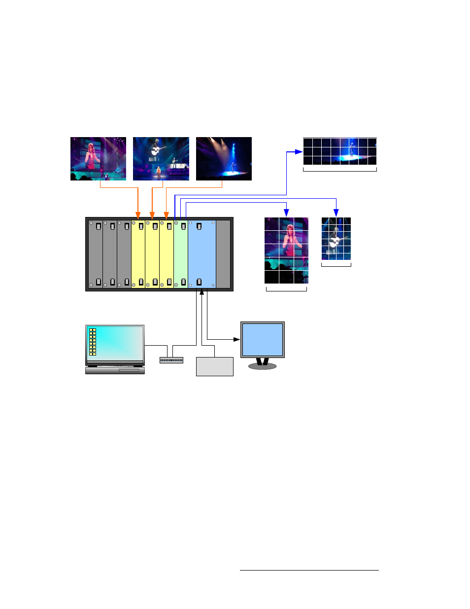
The figure below illustrates another sample DX-700 “single bank” configuration. In this
diagram, the bank consists of one output module and three input modules. Three different
input sources are mapped to the output module’s three output connections, and are used to
drive three video walls of different sizes and aspect ratios.
Figure 1-8. Sample system configuration: triple input, triple output (ungrouped)
Blan
k Pa
ne
l
Blan
k Pa
ne
l
Blan
k Pa
ne
l
Inp
u
t Mo
du
le
Inp
u
t Mo
du
le
O
u
tp
ut
Mo
du
le
Sy
s
te
m
Mo
d
u
le
Po
wer
Su
p
p
ly
Inp
u
t Mo
du
le
Source 1
Source 2
Source 3
LED Wall 1
OLite
LED Wall 2
ILite
LED Wall 3
MiTRIX
Sync
Generator
Laptop PC
(Director Toolset)
DVI or RGB
Monitor
Ethernet
Switch