Genlock inputs, Expansion lock output, Rgbhv monitor out – Barco DX-700 User Manual
Page 52: Hardware orientation
52
DX-700 • User’s Guide • Rev 02
2. Hardware Orientation
DX-700 Rear Panel
2) Latches
Two Latches are provided to ensure precise module insertion and extraction.
Care is required when inserting or removing modules. Refer to the “
” section on page 57 for instructions.
3) Genlock
Inputs
Two BNC connectors are provided for the DX-700’s Genlock Inputs, one each for
H / CS IN
and V IN. These connections enable the DX-700 to lock to an external
black burst or composite sync signal.
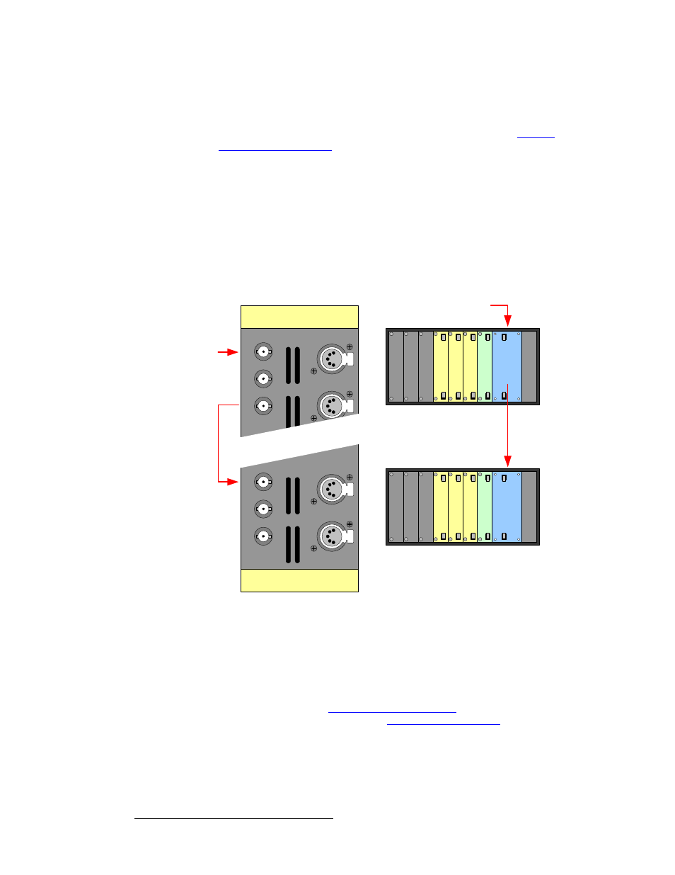
4) Expansion Lock Output
One BNC connector is provided for the DX-700’s Expansion Lock Output (EXP
LOCK
), a signal that enables the DX-700 to synchronize additional DX-700 units
— when external stacking is used. The EXP LOCK port (on the “master”)
connects to the H / CS IN connector on the first slave unit. Additional units can be
synchronized in this manner.
Figure 2-11.
Sample genlock configuration, external stacking
Note that when the EXP LOCK signal connects to a slave DX-700, it also serves
as a serial communication link between units to provide real-time command
execution across all connected DX-700s.
5) RGBHV Monitor Out
One 15-pin D connector is provided for the RGBHV Monitor Output. In
Appendix A, refer to the “
” section on page 179 for
RGB connector pinouts. Refer to the “
page 54 for additional information on both monitor output ports.
DM
X
TH
RU
DMX I
N
V I
N
H
/
C
S
IN
L
O
C
K
G
E
NLO
C
K
EXP
Unit 1
System Module
Unit 2
System Module
Input
Input
Input
Ou
tp
u
t
Sys
tem
Pow
e
r
Bl
a
n
k
Bl
a
n
k
Bl
a
n
k
Input
Input
Input
Ou
tp
u
t
Sys
te
m
Pow
e
r
Bl
an
k
Bl
an
k
Bl
an
k
Master
Slave
Genlock
Source
DM
X
TH
RU
DMX I
N
V I
N
H
/
CS
I
N
LO
CK
GENLOCK
EXP