Ethernet connector, Diagnostic connector, Ethernet connector diagnostic connector – Barco DX-700 User Manual
Page 183: Bíüéêåéí=`зеейензк, Aб~цезлнбе=`зеейензк, K==pééåáñáå~нбзел
DX-700 • User’s Guide • Rev 02
183
^K==péÉÅáÑáÅ~нбзел
Pinouts
bíÜÉêåÉí=`зееЙЕнзк
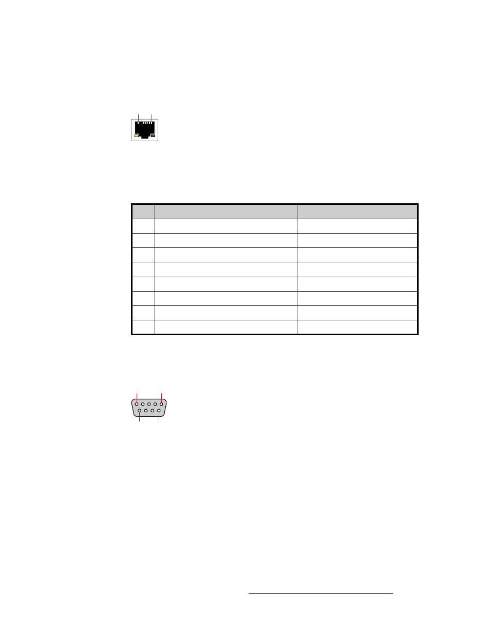
The figure below illustrates the Ethernet connector:
Figure A-4.
Ethernet connector
The table below lists Ethernet connector pinouts.
aб~ЦезлнбЕ=`зееЙЕнзк
The figure below illustrates the Diagnostic connector.
Figure A-5.
Diagnostic connector
The diagnostics port is reserved for factory and technical support use only.
Table A-5.
Ethernet Connector Pinouts
Pin
Signal
Wire Color
1
TX Data +
White / Orange
2
TX Data -
Orange
3
RX Data +
White / Green
4
Blue
5
White / Blue
6
RX Data -
Green
7
White / Brown
8
Brown
1
8
5
1
9
6