Dx-700 rear panel, Aujtmm=oй~к=m~åéä, Hardware orientation – Barco DX-700 User Manual
Page 40: The figure below illustrates the dx-700 rear panel
40
DX-700 • User’s Guide • Rev 02
2. Hardware Orientation
DX-700 Rear Panel
auJTMM=oЙ~к=m~åÉä
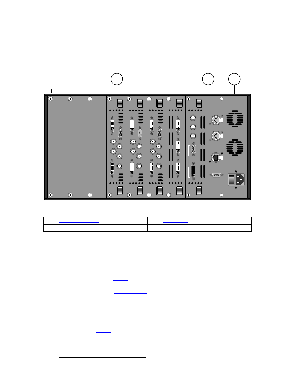
The figure below illustrates the DX-700 rear panel:
Figure 2-1. DX-700 Rear Panel, with sample DVI I/O configuration
Following are descriptions of each rear panel connector:
1)
Input / Output Section
The Input / Output Section provides seven slots for both input and output
modules, which can be arranged in a variety of configurations and “banks.” Each
module is fully shielded and field-installable.
~
A single “universal” input module is available. Refer to the “
” section on page 41 for details.
~
Two different output modules are available (DVI and NNI). Refer to the
“
” section on page 45 for details.
~
Refer to the “
” section on page 41 for important rules
governing the configuration and placement of modules.
2) System
Module
The System Module is standard on all DX-700 units. It provides connections for
synchronization, monitoring, control and diagnostics. Refer to the “
” section on page 51 for details.
1
2
3
EX
P O
U
T
DV
I
/ EXP
IN
RG
B
H
V
1
- HD
/S
DI
- 2
Y
/
C
O
M
P
C / Pb
P
r
EX
P O
U
T
DV
I
/ EXP
IN
RG
B
H
V
1
- HD
/S
DI
- 2
Y
/
C
O
M
P
C / Pb
P
r
EX
P O
U
T
DV
I
/ EXP
IN
RG
B
H
V
1
- HD
/S
DI
- 2
Y
/
C
O
M
P
C / Pb
P
r
LE
D O
U
T
1
LE
D O
U
T 2
L
E
D
O
U
T 3
100-240V
50-60 Hz, 5.0 A
DI
AG
NO
ST
IC
ET
HER
N
E
T
D
M
X
T
HRU
DM
X I
N
V IN
H /
C
S
IN
LO
CK
MO
NIT
O
R
GEN
L
OC
K
E
XP
1)
3)
2)