Appendix b, Appendix b. typical muting applications, Warning – Banner MMD-TA-11B Muting Modules User Manual
Page 48
46
P/N 116390 rev. C
Banner Engineering Corp.
•
Minneapolis, U.S.A.
www.bannerengineering.com • Tel: 763.544.3164
MMD-TA-11B / MMD-TA-12B Muting Module
Instruction Manual
Appendix B
Entry/Exit Applications
The muting devices must be placed to ensure that the points
that trigger the mute’s start and end are very close to the
safety light screen’s sensing field. This prevents personnel from
following, or being pushed by, the object into the hazardous
area without interrupting the safety light screen before the mute
window opens or at the time the mute window closes.
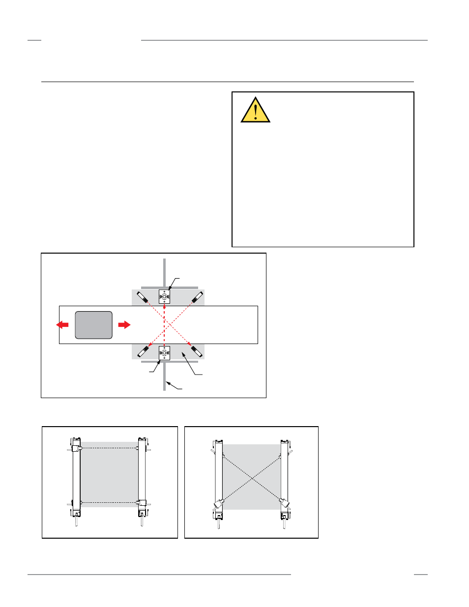
When two pairs of opposed-mode photoelectrics are used as
muting devices, as shown below, the crossing point of the two
sensing paths must be on the hazardous side of the safety
light screen. The safety light screen will be interrupted before
any personnel would be able to block both beams and mute
the system. The devices should detect the material and not the
pallet or the transport in order to hinder an individual from riding
into the hazardous area.
Carrier
Basket
Safe Area
(free movement
of personnel)
Hazardous Area
(which is being protected
from personnel entry)
Hard Guarding
Safety Mat or
Horizontally Mounted
Safety Light Screen
M1
M2
Light Screen
Receiver
Light Screen
Emitter
Figure B-1. “X”-Pattern Entry/Exit system using two pairs of opposed-mode
photoelectric muting devices
Figure B-2. Horizontal photoelectric muting
devices placed at different heights
Figure B-3. Photoelectric muting devices
placed diagonally
Light Screen
Defined Area
M1
(Receiver
Not
Shown)
M2
(Receiver)
M1
(Emitter)
M2
(Emitter
Not
Shown)
M1
(Emitter)
Light Screen
Defined Area
M1
(Receiver
Not
Shown)
M2
(Receiver)
M2
(Emitter
Not
Shown)
WARNING . . .
• It must not be possible for an individual to block both
photoelectric beams (dashed diagonal lines in Figure
B-1) and initiate a mute condition. Check the installation
to verify that unintentional muting is not possible. The
“crossing point” of the photoelectric beams must be
located in the hazardous area and not be accessible to
personnel (by reaching over, under, through, or around).
• It must not be possible for personnel to walk in front
of, behind, or next to the muted object (e.g., the carrier
basket) without being detected and stopping the
hazardous motion. Supplemental safeguarding must be
used to prevent personnel from entering the hazardous area
during a mute condition.
Appendix B. Typical Muting Applications