System installation, 3 ssi emergency stop switch device hookup, Warning – Banner MMD-TA-11B Muting Modules User Manual
Page 26
24
P/N 116390 rev. C
Banner Engineering Corp.
•
Minneapolis, U.S.A.
www.bannerengineering.com • Tel: 763.544.3164
MMD-TA-11B / MMD-TA-12B Muting Module
Instruction Manual
System Installation
Category 2
A single-channel emergency stop application typically provides
a category 2 level of circuit performance, because a short circuit
could cause the loss of the safety function. The principle of fault
exclusion must be incorporated into the design and installation
to either eliminate, or reduce to an acceptable (minimal) level of
risk, the possibility of undetected faults or failures that can result
in the loss of the safety function.
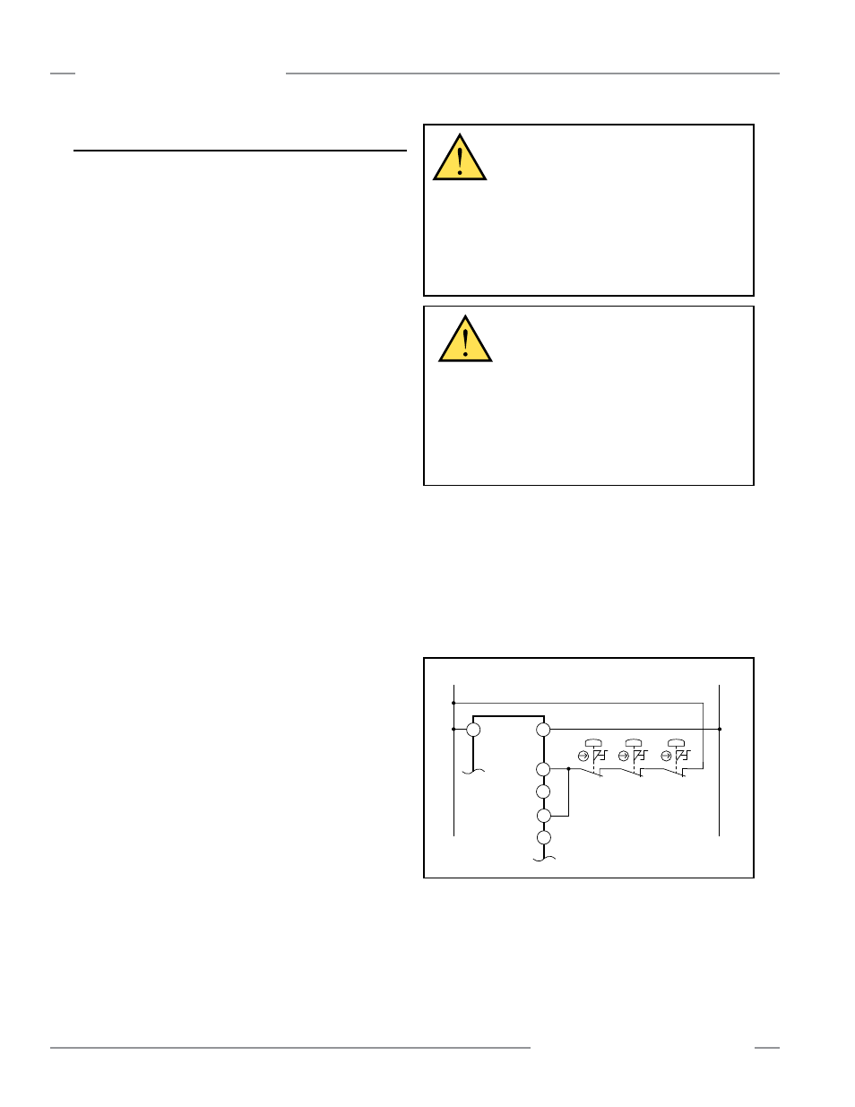
3.5.6.3 SSI Emergency Stop Switch Device Hookup
Emergency Stop Push Button Switches
As shown in Figures 3-16, 3-17 and 3-18, the E-stop switch must
provide one or two contacts for safety which are closed when
the switch is armed. Once activated, the E-stop switch must
open all its safety-rated contacts, and must require a deliberate
action (such as twisting, pulling, or unlocking) to return to the
closed-contact, armed position. The switch should be a “positive-
opening” (or direct-opening) type, as described by IEC 60947-5-1.
A mechanical force applied to such a button (or switch) is
transmitted directly to the contacts, forcing them open. This
ensures that the switch contacts will open whenever the switch
is activated.
Standards ANSI NFPA 79, IEC/EN 60204-1, and ISO 13850
specify additional emergency stop switch device requirements,
including the following:
• Emergency Stop push buttons shall be located at each operator
control station and at other operating stations where emergency
shutdown is required.
• Stop and Emergency Stop push buttons shall be continuously
operable and readily accessible from all control and operating
stations where located. Do not connect E-stop buttons to the
MSSI.
• Actuators of Emergency Stop devices shall be colored Red.
The background immediately around the device actuator shall
be colored Yellow. The actuator of a push-button-operated
device shall be of the palm or mushroom-head type.
• The Emergency Stop actuator shall be a self-latching type.
NOTE: Some applications may have additional requirements.
The user must comply with all relevant regulations.
Safety Circuit Integrity Levels and Emergency Stop functions
As part of the required risk assessment for the machine, ANSI
NFPA 79 and IEC/EN 60204-1 state that the safety performance
(integrity) must reduce the risk from identified hazards as
determined by the risk assessment. See Sections 3.5.6.1 and
3.5.6.2 for guidance if the requirements as described by ISO
13849-1 (EN954-1) are to be implemented.
In addition to the requirements stated above, the design and
the installation of the emergency stop device (e.g., switch,
button, or rope-pull) must be such that the possibility of a
catastrophic failure of the device resulting in the loss of
the safety function must be excluded (designed out). Per ISO
13849-2, electromechanical devices that have contacts designed
in accordance to IEC 60947-5-1 Annex K and that are installed
per manufacturer’s instructions are expected to open when the
emergency stop device is actuated.
Figure 3-16. SSI Category 2 interfacing: positive-opening
E-stop switch(es)
0V dc
+24V dc
X6 (a)
X5 (b)
X8 (c)
X7 (d)
A2
A1
SSI
MMD-TA-..B
WARNING . . .
Emergency Stop
Functions
Do not connect any device to the MSSI Input
that is used for an emergency stop function. Never mute
or bypass any emergency stop device (e.g., a button or
rope pull). ANSI NFPA 79 and IEC/EN 60204-1 require that
the emergency stop function remain active at all times.
Muting or bypassing the safety outputs will render the
Emergency Stop function ineffective.
WARNING . . .
Reset Routine
Required
U.S. and international standards require that a
reset routine be performed after returning the E-stop switch to
its closed-contact position (when arming the E-stop switch).
When automatic reset is used, an alternate means must be
established to require a reset routine, after the E-stop switch
is armed. Allowing the machine to restart as soon as the
E-stop switch is armed creates an unsafe condition which
could result in serious injury or death.