System installation, 1 mute enable hookup, 2 external device monitoring (edm) hookup – Banner MMD-TA-11B Muting Modules User Manual
Page 34: Caution
32
P/N 116390 rev. C
Banner Engineering Corp.
•
Minneapolis, U.S.A.
www.bannerengineering.com • Tel: 763.544.3164
MMD-TA-11B / MMD-TA-12B Muting Module
Instruction Manual
System Installation
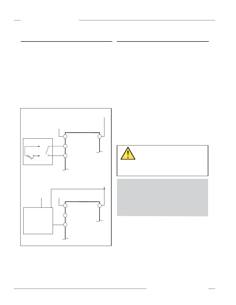
3.7.1 Mute Enable Hookup
The Module provides a Mute Enable input (“ME,” X13−X14) for
the connection of a potential free contact (see Section 1.12).
Mute Enable gives the user the ability to “frame” or create a
“window of opportunity” when a mute can occur. When
configured, the Mute Enable input is a contact that must be
closed before the safeguard can be muted. After the safeguard
is muted, opening of the Mute Enable input has no effect, but it
must be re-closed before the safeguard can be muted again.
To hook up a device (sensor or PLC output) with a solid state
output, see optional hookup in Figure 3-23.
If Mute Enable is not to be used, leave the factory-installed
jumper between X13–X14.
3.7.2 External Device Monitoring (EDM) Hookup
The Module provides connection terminals for the External
Device Monitoring input (EDM #1—Y1−Y2 and EDM #2—
Y3−Y4). External Device Monitoring must be wired in one of
three configurations:
• One-Channel Monitoring — SW4 Banks A and B = ON or 1 CH
(see Figures 3-26 and 3-28). NOTE: EDM #2 input must be left
open.
• Two-Channel Monitoring — SW4 Banks A and B = OFF or 2 CH
(see Figures 3-24, 3-25, and 3-27).
• No Monitoring — SW4 Banks A and B = OFF or 2 CH
NOTE: Terminal Y1 of EDM #1 must be jumpered to Y3 of
EDM #2.
After the initial checkout has been successfully completed, the
EDM configuration that disabled the monitoring function must
be properly reconfigured. The External Device Monitoring inputs
then must be properly connected to the closed monitoring
contacts of the MPCEs (see Section 1.10). Refer to the NOTICE
Regarding MPCE Monitoring Hookup, below, and Figures 3-24,
3-25, 3-26, 3-27, and 3-28.
A1
X13
+24V dc
0V dc
0V dc
or
Machine Control
X14
MMD-TA-..B
A2
A1
X13
+24V dc
+24V dc
0V dc
0V dc
Sensor or PLC
Optional Hookup
Semiconductor
PNP output
X14
MMD-TA-..B
A2
Figure 3-23. Mute Enable hookup
CAUTION . . .
EDM Configuration
If the application does not require this function,
the terminal Y1 of EDM #1 must be jumpered to
Y3 of EDM #2 (see Section 3.7.2). It is the user’s responsibility
to ensure that this does not create a hazardous situation.
NOTICE Regarding External Device Monitoring Hookup
It is strongly recommended that one normally closed,
forced-guided, monitoring contact of each MPCE or external
device be wired in order to monitor the state of the MPCEs
(as shown in Figures 3-24 to 3-28). If this is done, proper
operation of the MPCEs will be verified. MPCE monitoring
contacts must be used in order to maintain control reliability.