System installation, Warning, 3 mute lamp output (ml) – Banner MMD-TA-11B Muting Modules User Manual
Page 22: 4 auxiliary output (aux), 5 override switch hookup
20
P/N 116390 rev. C
Banner Engineering Corp.
•
Minneapolis, U.S.A.
www.bannerengineering.com • Tel: 763.544.3164
MMD-TA-11B / MMD-TA-12B Muting Module
Instruction Manual
System Installation
Override A
Override B
X9
X10
X11
X12
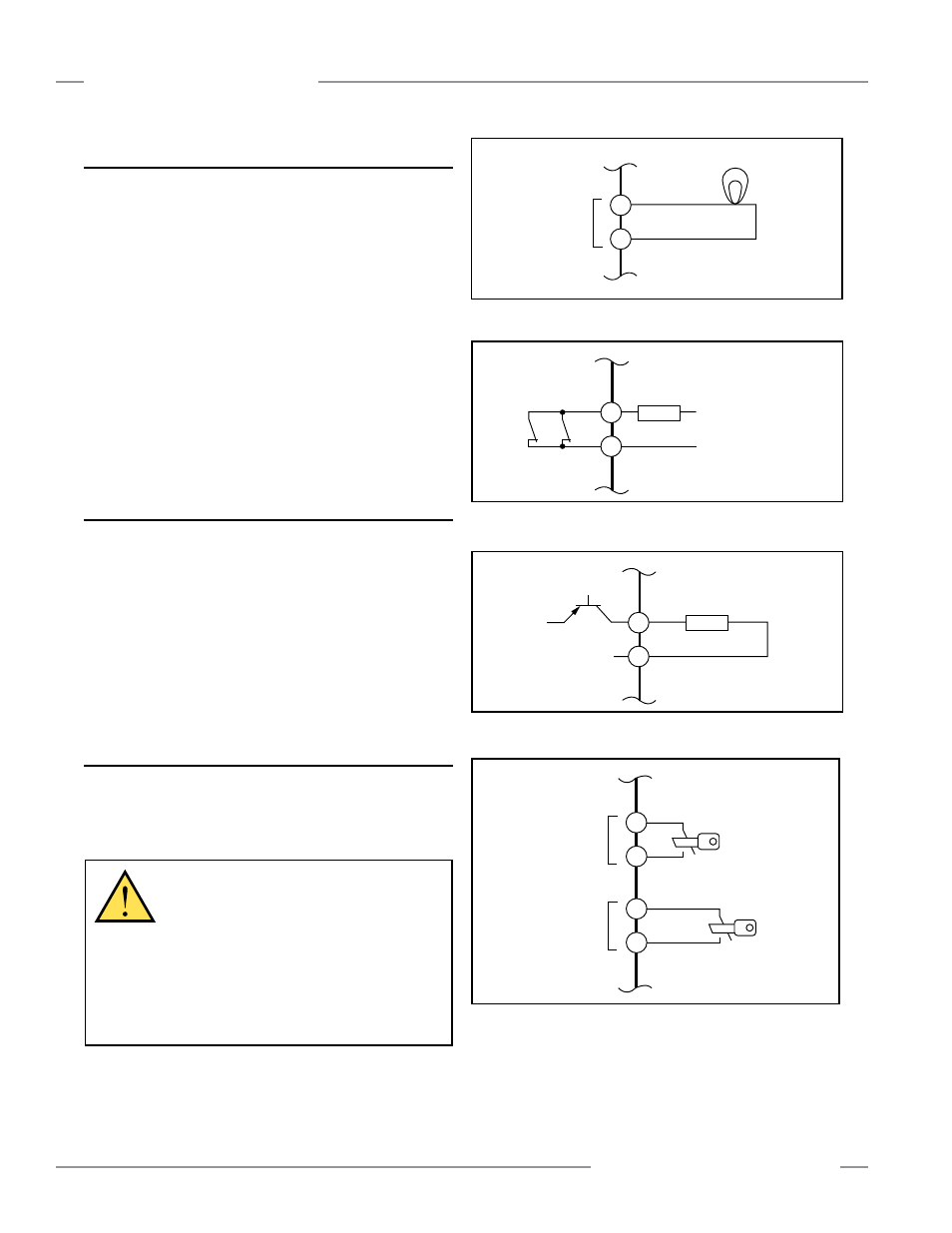
Figure 3-12. Override switch hookup
WARNING . . .
Limit Use of Override
Function
The Override function is not for machine setup
or production; it is to be used only to clear the primary
safeguard if material becomes “stuck,” preventing
its reset. When Override is used, it is the user’s
responsibility to install and use it according to current
standards. In addition, the requirements listed in standards
ANSI NFPA 79 and IEC/EN 60204-1 must be satisfied.
Mute
Lamp
X3
X4
+
+
-
+V
0V
Z4
Z3
Load
Figure 3-10. Mute Lamp output hookup
Figure 3-11b. AUX output hookup – MMD-TA-12B
3.5.3 Mute Lamp Output (ML)
The Mute Lamp output provides for the visible indication that the
safety device’s safeguarding function is muted. This indication
must be readily observable. Failure of this indication should be
detectable and prevent the safeguard from being muted, or the
operation of the indicator should be verified at suitable intervals
(see Section 1.13). The Mute Lamp output also flashes to
indicate an Override condition (see Section 1.16).
The Module can be configured for a monitored or non-monitored
mute lamp. It is the user’s responsibility to make sure that each
application meets local regulations. If the installation is governed
by UL regulations, the mute lamp must be monitored (SW7 =
OFF, banks A and B). This output may also be used as an input
to control logic (e.g., a PLC) if “non-monitored” is selected (SW7
= ON, banks A and B). The current draw of the mute lamp must
not exceed 360 mA. See Figure 3-10.
3.5.4 Auxiliary Output (AUX)
Model MMD-TA-11B: The non-safety-related output on this
model is a 24V ac/dc, 250 mA normally-closed relay contact.
See Output Specifications on page 9. See Figure 3-11a.
Model MMD-TA-12B: A non-safety-related PNP output is
available at terminals Z3–Z4. This monitoring output is for light-
duty, non-safety-related control functions, such as an input to
a programmable logic controller (PLC). This output follows the
OSSD outputs. Maximum current draw of the AUX output is
250 mA. See Figure 3-11b.
3.5.5 Override Switch Hookup
The Module provides connection terminals for the Override
switches (see Figure 3-12). See Section 1.16 and the warning
below before connecting switches.
V+
0V
K1
K2
31
32
Load
Figure 3-11a. AUX output hookup – MMD-TA-11B