System installation, 4 connection terminals and functions, Warning – Banner MMD-TA-11B Muting Modules User Manual
Page 18: Proper electrical hookup, Mmd-ta-11b / mmd-ta-12b muting module
16
P/N 116390 rev. C
Banner Engineering Corp.
•
Minneapolis, U.S.A.
www.bannerengineering.com • Tel: 763.544.3164
MMD-TA-11B / MMD-TA-12B Muting Module
Instruction Manual
System Installation
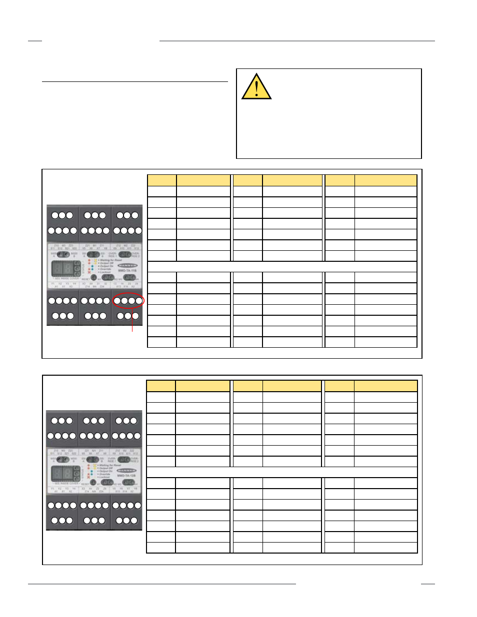
3.4 Connection Terminals and Functions
All electrical connections are made through removable terminals
(see Figures 3-4a and 3-4b).
To disable the SSI, terminal X5 (SSIb) must be jumpered to
terminal X6 (SSIa), and terminal X7 (SSId) must be jumpered to
terminal X8 (SSIc) (factory default). Do not short Channel A to
Channel B.
WARNING . . .
Proper Electrical
Hookup
Electrical hookup must be made by Qualified
Personnel and must comply with NEC (National Electrical
Code) and local standards.
Make no connections to the System other than those
described in Section 3 of this manual. Doing so could result
in serious injury or death.
Figure 3-4a. MMD-TA-11B terminal connection locations
A1
X1 X2
S11 S12 S21 S22
Z21 M1 Z11
X5 X6
X7 X8
Z12 M2 Z22
Z13 M3 Z23
Z14 M4 Z24
X13 X14 A2
X9 X10 X11 X12
Y1 Y2 Y3 Y4
X3 X4
Z3
Z4
Y5
Y6
Y7 Y8
Terminal
Function
Terminal
Function
Terminal
Function
Z13
M3, 0V
Z21
M1, 24V
Z12
M2, 0V
M3
Muting 3 In (PNP)
M1
Muting 1 In (PNP)
M2
Muting 2 In (NPN)
Z23
M3, 24V
Z11
M1, 0V
Z22
M2, 24V
S11
MSSI b (ch A)
X5
SSI b (ch A)
X9
Override a (ch A)*
S12
MSSI a (ch A)
X6
SSI a (ch A)
X10
Override b (ch A)*
S21
MSSI d (ch B)
X7
SSI d (ch B)
X11
Override c (ch B)*
S22
MSSI c (ch B)
X8
SSI c (ch B)
X12
Override d (ch B)*
Y1
EDM 1 a Out (24V)
X3
Mute Lamp Out (24V)
Y5
OSSD 1 a Out
Y2
EDM 1 b In
X4
Mute Lamp In
Y6
OSSD 1 b 0V
Y3
EDM 2 b In
Z3
AUX b 0V
Y7
OSSD 2 b 0V
Y4
EDM 2 a Out (24V)
Z4
AUX a Out
Y8
OSSD 2 a Out
A1
+24V dc
Z14
M4, 0V
X13
Mute Enable Out (24V)
X1
Reset In
M4
Muting 4 In (NPN)
X14
Mute Enable In
X2
Reset Out (24V)
Z24
M4, 24V
A2
0V dc
All terminals are low-voltage
Figure 3-4b. MMD-TA-12B terminal connection locations
*contacts only
Potential
High-Voltage
Terminals
A1
X1 X2
S11 S12 S21 S22
Z21 M1 Z11
X5 X6 X7 X8
Z12 M2 Z22
Z13 M3 Z23
Z14 M4 Z24
X13 X14 A2
X9 X10 X11 X12
Y1 Y2 Y3 Y4
X3 X4 31 32
13
14
23 24
All terminals are low-voltage,
except for those indicated
otherwise
Terminal
Function
Terminal
Function
Terminal
Function
Z13
M3, 0V
Z21
M1, 24V
Z12
M2, 0V
M3
Muting 3 In (PNP)
M1
Muting 1 In (PNP)
M2
Muting 2 In (NPN)
Z23
M3, 24V
Z11
M1, 0V
Z22
M2, 24V
S11
MSSI b (ch A)
X5
SSI b (ch A)
X9
Override a (ch A)*
S12
MSSI a (ch A)
X6
SSI a (ch A)
X10
Override b (ch A)*
S21
MSSI d (ch B)
X7
SSI d (ch B)
X11
Override c (ch B)*
S22
MSSI c (ch B)
X8
SSI c (ch B)
X12
Override d (ch B)*
Y1
EDM 1 a Out (24V)
X3
Mute Lamp Out (24V)
13
OSSD 1 a (Relay)
Y2
EDM 1 b In
X4
Mute Lamp In
14
OSSD 1 b (Relay)
Y3
EDM 2 b In
31
AUX a (Relay)
23
OSSD 2 a (Relay)
Y4
EDM 2 a Out (24V)
32
AUX b (Relay)
24
OSSD 2 b (Relay)
A1
+24V dc
Z14
M4, 0V
X13
Mute Enable Out (24V)
X1
Reset In
M4
Muting 4 In (NPN)
X14
Mute Enable In
X2
Reset Out (24V)
Z24
M4, 24V
A2
0V dc
*contacts only