Appendix a, Appendix a. mute timing sequences, Mmd-ta-11b / mmd-ta-12b muting module – Banner MMD-TA-11B Muting Modules User Manual
Page 47: Instruction manual
P/N 116390 rev. C
45
Banner Engineering Corp.
•
Minneapolis, U.S.A.
www.bannerengineering.com • Tel: 763.544.3164
MMD-TA-11B / MMD-TA-12B Muting Module
Instruction Manual
Appendix A
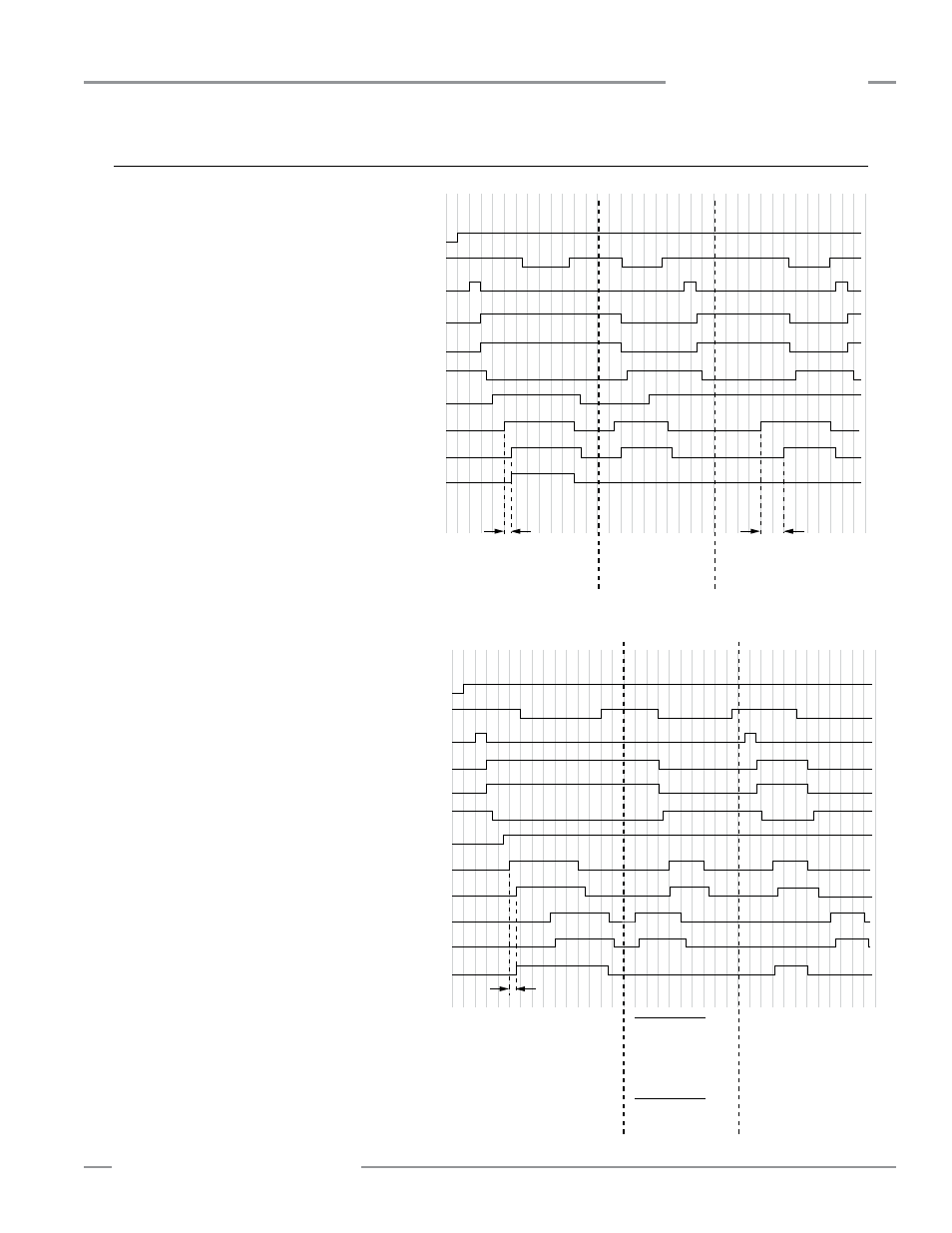
Appendix A. Mute Timing Sequences
{
Power
ON
Open
Closed
Closed
Closed
Closed
MSSI
Closed
Reset
Reset
Reset
Open
Open
Open
Less than
3 seconds
Normal mute cycle
OSSD outputs
remain ON
Mute cycle prevented
due to open
Mute Enable input
Mute cycle prevented
due to simultaneity
not being met
EDM
Open
Mute Enable
M1
Mute
Inputs
Closed
Mute
M2
Mute Cycle
System Reset
More than
3 seconds
OFF
(open)
OFF (open)
OFF (open)
ON (closed)
OFF
(open)
OFF (open)
OFF (open)
ON (closed)
OSSD Outputs
AUX Outputs
MMD-TA-11B
Closed
One-Way Muting:
{
{
Power
ON
OFF
(open)
OFF
(open)
Open
OFF (open)
OFF (open)
ON (closed)
OFF (open)
OFF (open)
ON (closed)
Closed
MSSI
Closed
Reset
Reset
Open
Open
Open
OSSD Outputs
Less than
3 seconds
Normal mute cycle
OSSD outputs
remain ON
Mute cycle drops out
and the OSSD outputs open due
to M3 and M4 not closing before
M1 or M2 open, when the
defined area is blocked.
Since one-way muting has been
selected, M3 and M4 can not
initiate a mute cycle.
EDM
Open
Mute Enable
M1
Mute
Inputs
Closed
Closed
Mute
M2
Mute Cycle
System Reset
M3
Mute
Inputs
M4
Closed
Mute
Mute cycle prevented
due to mute devices
M3 and M4 closing
before M1 and M2.
Two-Way Muting:
A normal mute cycle
would occur.
NOTE: A mute cycle begins 100 ms after the second
mute input becomes active, if all other
conditions are met.
AUX Outputs
MMD-TA-11B
Muting Sequence with Four Muting Devices
(For example, an Entry/Exit System using four
photoelectric devices; see Figure B-5)
DIP Switch Configuration*:
MSSI Auto or Manual Reset. . . .SW1 = OFF (Manual)
SSI Auto or Manual Reset . . . . .SW2 = OFF (Manual)
or ON (Auto)
One-Way Muting . . . . . . . . . . . .SW3 = OFF (1-way)
Two-/One-Channel EDM . . . . . .SW4 = OFF (2 CH)
Backdoor Timer . . . . . . . . . . . . .SW5&6 = OFF (30 sec.)
Monitored Muting Lamp . . . . . . .SW7 = OFF (Mon)
Mute on Power-up . . . . . . . . . . .SW8 = OFF (Disable)
*Both DIP switch banks A and B.
Muting Sequence with Two Muting Devices
(For example, “X”-pattern Entry/Exit System,
see Figure B-1)
DIP Switch Configuration*:
MSSI Auto or Manual Reset. . . .SW1 = OFF (Manual)
SSI Auto or Manual Reset . . . . .SW2 = OFF (Manual)
or ON (Auto)
One-Way Muting . . . . . . . . . . . .SW3 = OFF (1-way)
Two-/One-Channel EDM . . . . . .SW4 = OFF (2 CH)
Backdoor Timer . . . . . . . . . . . . .SW5&6 = OFF (30 sec.)
Monitored Muting Lamp . . . . . . .SW7 = OFF (Mon)
Mute on Power-up . . . . . . . . . . .SW8 = OFF (Disable)
*Both DIP switch banks A and B.