System installation, Warning – Banner MMD-TA-11B Muting Modules User Manual
Page 19
P/N 116390 rev. C
17
Banner Engineering Corp.
•
Minneapolis, U.S.A.
www.bannerengineering.com • Tel: 763.544.3164
MMD-TA-11B / MMD-TA-12B Muting Module
Instruction Manual
System Installation
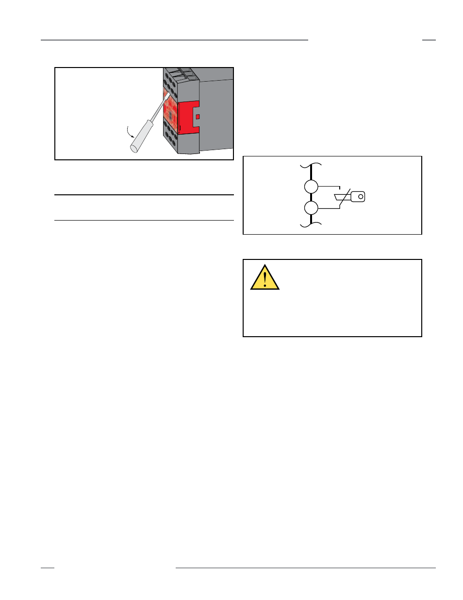
Figure 3-5. Removal of terminal blocks
3.5 Installing Input Devices
3.5.1 Manual Reset Switch
The manual reset switch connects to Module terminals X1 and
X2 (see Figure 3-6). See Section 3.3 for Auto/Manual Reset
configuration.
Any reset switches must be located so that a reset is possible
only from outside, and in full view of, the hazardous area. The
switch must also be out of reach from within the safeguarded
space. If any hazardous areas are out of view from the switch
location, additional means of safeguarding must be provided.
The switch must be protected from accidental or unintended
actuation (e.g., through the use of rings or guards).
Using a key switch provides some level of personal control,
because the key may be removed. This will hinder a reset while
the key is under the control of an individual, but must not be
relied upon solely to guard against accidental or unauthorized
reset. Spare keys in the possession of others, or additional
personnel entering the safeguarded area unnoticed may create a
hazardous situation.
Reset Routine
The Muting Module requires a manual reset to clear a latch
condition and resume operation following a stop command. To
perform a manual reset, close the normally open reset switch
and hold it there for at least 1/4 second, but not longer than 2
seconds, and then re-open the switch. Internal lockout conditions
also require a manual reset to return the system to RUN mode
after the failure has been corrected and the input correctly
cycled.
X1
X2
Figure 3-6. Manual Reset switch connections
WARNING . . .
Location of the
Manual Reset Switch
The reset switch must be located outside of,
and not be accessible from within, the dangerous area,
and it must be positioned so that the dangerous area
may be observed by the switch operator during the reset
operation.
To remove a terminal block, insert
a small screwdriver into the slot
shown, and pry to loosen.
When reinserting a terminal block,
take care to slide the dovetail on
the terminal block into the slot on
the frame.