Operating instructions, Warning, 1 security protocol – Banner MMD-TA-11B Muting Modules User Manual
Page 41: 2 periodic checkout requirements, 3 normal operation
P/N 116390 rev. C
39
Banner Engineering Corp.
•
Minneapolis, U.S.A.
www.bannerengineering.com • Tel: 763.544.3164
MMD-TA-11B / MMD-TA-12B Muting Module
Instruction Manual
Operating Instructions
WARNING . . .
Verify Proper Operation
The Muting Module and safety systems can do
the job for which it was designed only if it and
the machine it guards are operating properly, both separately
and together. It is the user’s responsibility to verify proper
operation, on a regular basis, as instructed in Section 6.
If the Muting Module, safety systems, and the guarded
machine do not perform exactly as outlined in the
checkout procedures, the cause of the problem must be
found and corrected before the system is put back into
service.
Failure to correct such problems can result in serious
bodily injury or death.
WARNING . . .
Power Failures
Power failures or other Module lockout
conditions should always be investigated
immediately by a Qualified Person. A lockout is a definite
indication of a problem and should be investigated at
once. Attempts to continue to operate machinery by
bypassing the Module are dangerous and could result in
serious bodily injury or death.
4.1 Security Protocol
The Module must be mounted inside a lockable enclosure or
cabinet rated IP54 or better, both to protect the Module from
environmental conditions and in order to prevent access by
unauthorized personnel, if required by applicable standards.
The key (or combination) to the enclosure should be kept in
the possession of a Qualified Person and only they should
have access to the configuration switches. A Qualified Person
is defined as an individual who, by possession of a recognized
degree or certificate of professional training, or who, by
extensive knowledge, training, and experience, has successfully
demonstrated the ability to solve problems relating to the subject
matter and work.
4.2 Periodic Checkout Requirements
In addition to the checkouts that are performed by a Qualified
Person or persons at the time that the Module is installed and
put into service, the functioning of the safeguarding and the
machine must be verified on a regular periodic basis to ensure
proper operation. This is absolutely vital and necessary. Failure
to ensure proper operation can lead to serious injury or death.
See Section 6 for checkout schedules and procedures.
4. Operating Instructions
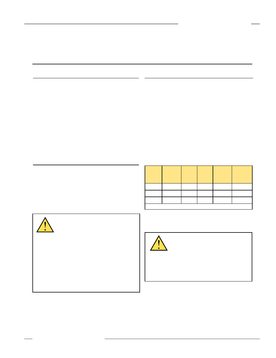
Figure 4-1. Muting module status indicator conditions
Waiting
for
Reset*
Output
OFF
Output
ON
Override Lockout
Red
ON
ON
OFF
ON
Flashing
Green
OFF
OFF
ON
ON
OFF
Yellow
Flashing
ON
OFF
OFF
OFF
* If either MSSI or SSI set to MANUAL, the red Status LED will be OFF at power-up.
4.3 Normal Operation
During normal operation, the Module’s three status indicators
(red, green and yellow) are as shown in Figure 4-1. In addition,
green and yellow indicators adjacent to each of the Module’s
inputs/interfaces come ON to verify an active state of that circuit.
During normal operation, the Diagnostic Display will read “—”
(solid or, if during the mute cycle, flashing). If the 30- or 60-
second Backdoor Timer feature is selected, the Diagnostic
Display will begin to count down in seconds. If the 30-minute
Backdoor Timer feature is selected, the timer countdown is
in minutes. A flashing dash will appear on the display if the
Backdoor Timer is OFF (infinite). If the Red status indicator
begins to flash, the number that appears in the Display signifies
an error; see Section 5.2 for more information.
See Section 3.5.1 for information on the reset routine.