System diagrams – Diode LED DAZZLE 24 RGBW Zone Controller User Manual
Page 4
INSTALLATION GUIDE
RGBW ZONE COLOR CONTROLLER
4 of 4
IG022614-1.0
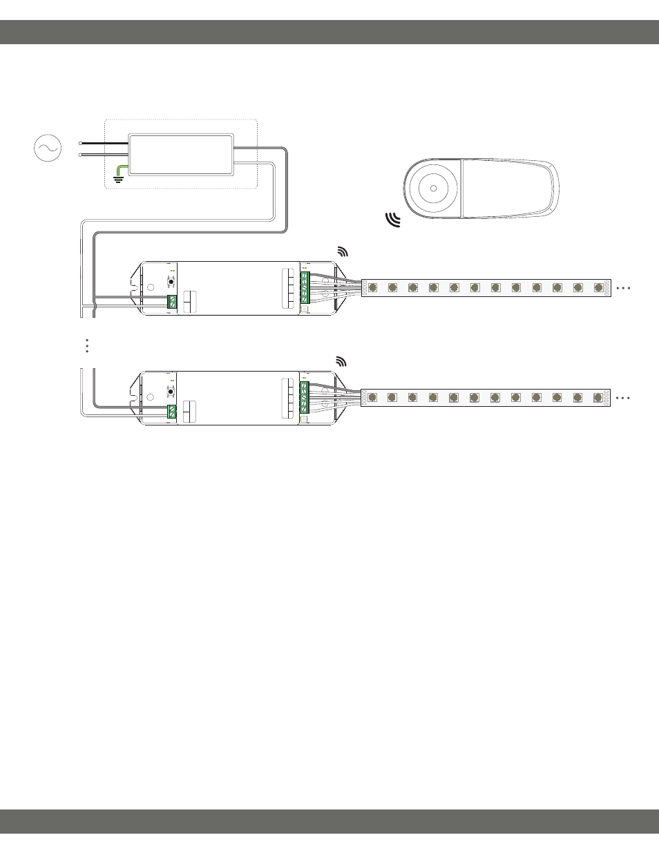
System Diagrams
W
B
G
R
V+
Ou
tpu
t
DC+
DC−
Power
Ad
dress
Setting
N
U
R
Ins
tall applic
able wire gauge / type
AC Power
50/60Hz
L
N
Class 2 Low Voltage Driver***
Installed in Junction Box‡
G*
N
L
Input
Output
V+
V-
V- V+
V- V+
Zone Receiver****
Zone Remote
♦
RF
V+
W
B
G
R
RGBW Strip Light / Fixture‡‡
W
B
G
R
V+
Ou
tpu
t
DC+
DC−
Power
Ad
dress
Setting
N
U
R
RGBW Strip Light / Fixture‡‡
V+
W
B
G
R
Zone Receiver****
The following diagram is provided as an example system design. Class 2 compliance may require a Class 2 driver per zone receiver (eg. 60W @ 12V, 96W
@ 24V). Install in accordance with the NEC, and local regulations.
* Driver may not require a fault ground connection. Refer to driver specifications for additional information.
*** Install a Class 2 constant voltage driver compatible with a low voltage PWM controller. It is recommended to load the driver no more than 80% its
labeled rating for maximum longevity.
**** Determine the number of low voltage outputs of the driver when installing multiple PWM controllers/dimmer switches. No more than one PWM
controller/dimmer switch can be attached to a single output of the driver.
♦ Zone remote has 8 total zones and may be paired to 8 total receivers (max 1 receiver per zone). Multiple remotes cannot be paired to a single receiver
(max 1 remote per receiver).
For additional questions/concerns, contact technical support. Please have all part numbers on hand for fast and efficient technical assistance.