Diode LED RGB Zone Control User Manual
Warning, Safety & warnings, Installation quick specs
1.877.817.6028
www.DiodeLED.com
www.DiodeLED.com
INSTALLATION GUIDE
1 OF 4
RGB ZONE COLOR CONTROLLER
®
• Install in accordance with the National Electric Code, and local
regulations.
• This product is intended to be installed and serviced by a qualified,
licensed electrician.
• DO NOT connect directly to high voltage power. Install with a compatible
Class 2 constant voltage LED driver (power supply).
• Only install compatible LED drivers and fixtures. Contact technical
support or visit the product page for compatible products.
• This product is rated for indoor installation and is not protected against
moisture.
• Proper heat dissipation will prolong the working lifespan of this product.
Install in a well-ventilated area free from explosive gases and vapors.
• Ensure applicable wire is installed between driver, fixture, and any
controls in between. When choosing wire, factor in voltage drop,
amperage rating, and type (in-wall rated, wet location rated, etc.).
Inadequate wire installation could overhead wires, and cause a fire.
• Do not modify or disassemble this product beyond instructions or the
warranty will be void.
Safety & Warnings
Prior to installation, verify all components are a compatible system. Configure and pre-test your LED system prior to permanent installation to ensure all
components are operating correctly. Install in accordance with the NEC and local regulations.
Installation
Quick Specs
Input / Output Voltage
5-24VDC constant voltage
Max Current Load
5A x 4CH Max 20A
Max Output Power
100W/240W/480W (5V/12V/24V)
Ambient Temperature
-22°
~ 131°F (-30° ~ 55°C)
Environment
Indoor / dry location
Input Voltage
5VDC Built-in Lithium Battery
Transmitting Distance
90 ft.
Control Type
Pulse Width Modulation (PWM)
3-channel RGB fixtures
Ambient Temperature †
-4°
~ 131°F (-20° ~ 55°C)
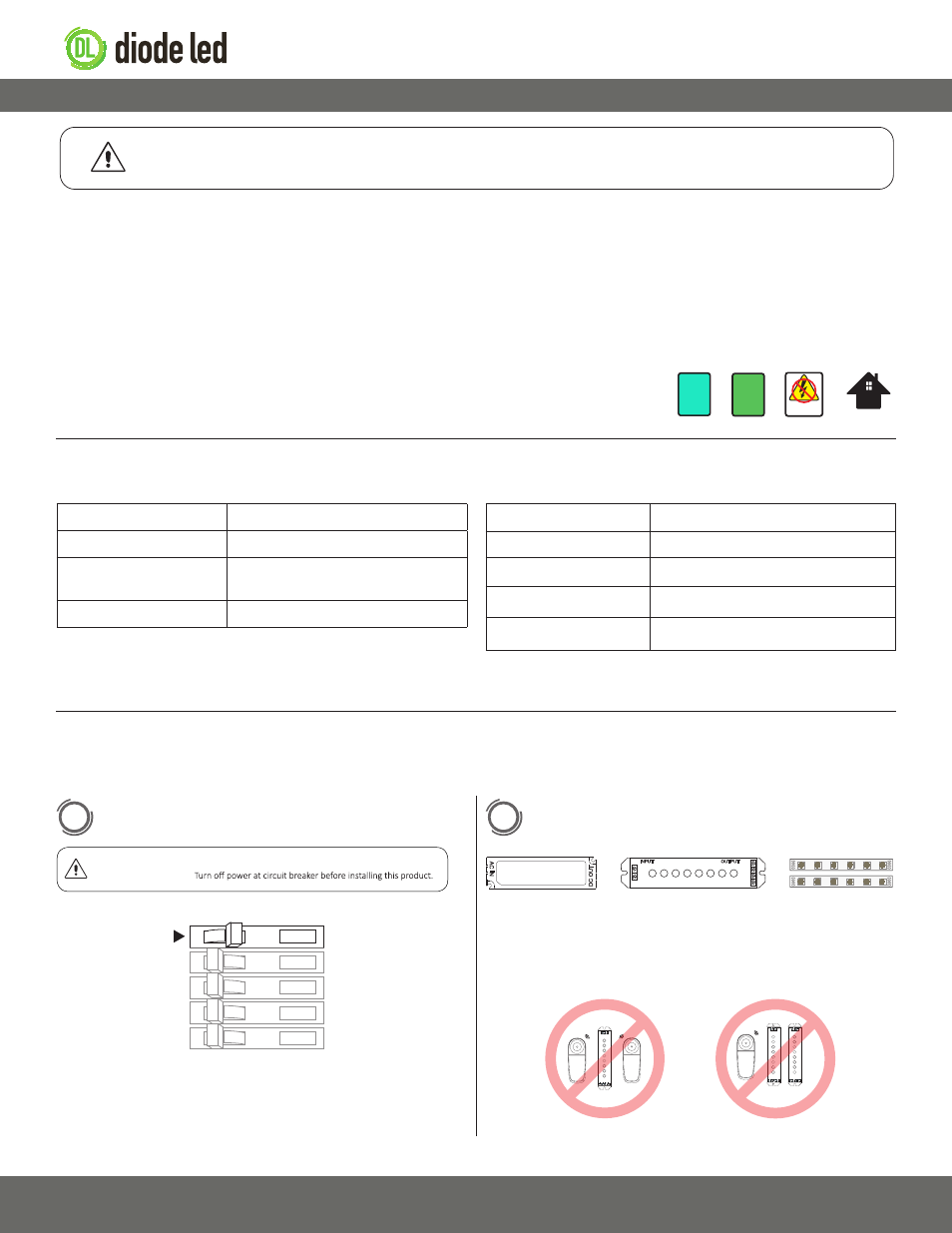
Turn OFF High Voltage AC Power at the main breaker.
Determine Locations to Install 3 Main Components.
Refer to the ‘System Diagrams.’
1
ON
OFF
OFF
OFF
ON
ON
OFF
OFF
ON
ON
2
V+
V-
V+
B
G
R
1) Driver
2) RGB Color
Controller
3) Fixture
Ensure applicable wire is installed between driver, fixture, and any
controls in between. When choosing wire, factor in voltage drop,
amperage rating, and type (in-wall rated, wet location rated, etc.).
DO NOT CONNECT DIRECTLY TO HIGH VOLTAGE POWER!
Read all warnings and installation instructions thoroughly.
WARNING
WARNING
Shock Hazard. May result in serious injury or death.
DO NOT CONNECT
TO HIGH VOLTAGE
Dry Location Only
12V
DC
24V
DC
RGB Zone Remote
RGB Zone Receiver
For full specifications, see the ‘Specification Sheet’ available at the online
product page.
† Do not install product in an environment outside the listed ambient
temperature. Ensure adequate airflow and heatsinking is considered
when mounting/installing.
DC+
DC-
V+
B
G
R
RF
RF
DO NOT PAIR MULTIPLE
REMOTES TO A SINGLE RECEIVER.
Zone 1
Zone 1
DC+
DC-
V+
B
G
R
DC+
DC-
V+
B
G
R
RF
DO NOT SET MULTIPLE
RECEIVERS TO THE SAME ZONE.
IG060914-1.2
# DI-1700
# DI-1701