Diode LED Lutron Hi-Lume L3D User Manual
Warning, Required components install the ulr listed driver, L3d 3-wire and ecosystemr ulr listed driver
Need Help? www.lutron.com/hilumeled or call the Lutron LED Center of Excellence at 1.877.346.5338
L3D 3-Wire and EcoSystemR
ULR Listed Driver |
Installation
Important Notes:
Please read before installing.
• For installation by a qualified electrician in accordance with all local and
national electrical codes.
• Use copper conductors only.
• For indoor use only.
• For 277 V~ applications, a suitable barrier should be installed between
the input and Class 2 wiring per local and national electrical wiring codes.
• Check to see that the driver type and rating are suitable for the
application.
• DO NOT install if product has any visible damage.
• If moisture or condensation is evident, allow the product to dry completely
before installation.
• Operate between 32 °F (0 °C) and 104 °F (40 °C).
• 0% to 90% humidity, non-condensing.
For each system ensure you have:
At least one ULR Listed Hi-LumeR A-Series L3D Driver
3
One Compatible Lutron Control
1, 2
Required Components
Install the ULR Listed Driver
041436
Rev. A
01/2014
6
Driver and junction box must be grounded in accordance with local and national electrical codes. Ground provided by grounding of junction box and by using the green ground wire connection.
1
See list of compatible controls on reverse side.
2
Please refer to Installation Sheet with your control
for wiring instructions.
Lutron Electronics Co., Inc. | 7200 Suter Road
Coopersburg PA, 18036-1299
At least one compatible LED Load (light engine)
4, 5
L3DA4U1UKL-AV120 (12 V)
L3DA4U1UKL-CV240 (24 V)
L3DA4U1UKL-XXXXX
120 – 277 V~ 50 / 60 Hz ULR Listed Driver
3
Driver output range is factory-set.
Different output ratings are available for different loads.
4
5 W minimum.
5
Load ratings must match driver output ratings.
English
+
+
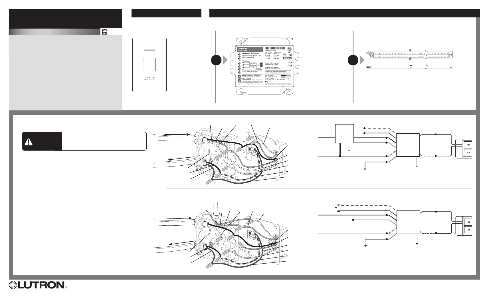
When installing the ULR Listed Driver,
wire as shown.
1. Remove driver and mounting plate from the rest of the junction box.
Do not remove driver from mounting plate.
2. Using leads and ground (bundled in junction box) make power, load,
and ground connections with provided wire nuts
(see wiring diagrams). Cap off any unused wires.
3. Re-install LED driver and mounting plate to the junction box.
4. Ensure compatible dimmer and load are installed and restore power
to circuit. See reverse side for Compatible Controls.
WARNING
Shock Hazard. May result in serious injury
or death. Turn off power at circuit breaker
before installing the unit.
Lutron
R
3-Wire
Forward
Phase
Dimmer
LED Light
Engine
Switched Hot (Black)
Dimmed Hot (Orange)
Hot
+ V (Red)
- V
(Black with
white stripe)
Neutral (White)
Neutral
(White)
Neutral
Ground
6
Ground
5
Ground (Green)
6
E1 (Purple / White)
E2 (Purple)
LED Light
Engine
Hot (Black)
Dimmed Hot (Orange)
+ V (Red)
- V
(Black with
white stripe)
Neutral (White)
Ground
6
Ground (Green)
6
E1 (Purple / White)
E2 (Purple)
To
EcoSystemR
Digital Link
3-Wire Controls
120 V~ / 277 V~ 50/60 Hz
From Line / Control
To LED
Load
Neutral
- LED
+ LED
Bare
Dimmed
Hot
Switched
Hot
Ground (Green)
- V (Black with White Stripe)
+ V (Red)
Neutral (White)
Dimmed Hot
(Orange)
Switched Hot
(Black)
Purple with
White Stripe
Purple
EcoSystemR Controls
120 V~ / 277 V~ 50/60 Hz
From Line
To LED
Load
Neutral
- LED
+ LED
Bare
E2
E1
Ground (Green)
- V (Black with White Stripe)
+ V (Red)
Neutral (White)
Dimmed Hot
(Orange)
Switched Hot
(Black)
Purple with
White Stripe
Purple
Hot
From EcoSystemR Control
3-Wire Wiring Diagram
EcoSystemR Wiring Diagram
OR
+ LED
- LED
+ LED
- LED
ULR Listed
Hi-lumeR
A-Series LED
Dimming
Driver
ULR Listed
Hi-lumeR
A-Series LED
Dimming
Driver