Diode LED Dimmable Driver 0-10V User Manual
Warning, Safety & warnings, Quick specs installation wiring connections
1.877.817.6028
www.DiodeLED.com
www.DiodeLED.com
INSTALLATION GUIDE
1 OF 4
0-10V DIMMABLE LED DRIVER
®
• Install in accordance with the National Electric Code, and local
regulations.
• This product is intended to be installed and serviced by a qualified,
licensed electrician.
• Only install compatible LED fixtures and controls. Contact technical
support or visit the product page for compatible products.
• Proper heat dissipation will prolong the working lifespan of this product.
Install in a well-ventilated area free from explosive gases and vapors.
• Ensure applicable wire is installed between driver, fixture, and any
controls in between. When choosing wire, factor in voltage drop,
amperage rating, and type (in-wall rated, wet location rated, etc.).
Inadequate wire installation could overheat wires, and cause a fire.
• Do not install if product has any visible damage.
• Do not modify or disassemble this product beyond instructions or the
warranty will be void.
Safety & Warnings
Dry/Wet
Location
Dimmable
Read all warnings and installation instructions thoroughly.
WARNING
IG072914-1.2
Prior to installation, ensure all components are a compatible system. Configure and pre-test your LED system prior to permanent installation to ensure
all components are operating correctly. Install in accordance with the NEC and local regulations.
1. Turn OFF 120
~277VAC power at the main breaker prior to installation.
2. Determine locations to install the driver, fixture and control. See ‘System Diagram.’
3. Attach appropriate load and 0-10V control/dimmer to the driver. See ‘Wiring Connections.’
4. Install additional components and accessories. Once complete, turn main power ON.
Input Voltage
100-277VAC~ at 50/60Hz
Output Voltage
See driver label for output voltage.
Ambient Temp †
-40 ~ +122°F (-40 ~ +50°C)
Max Load
Ensure to de-rate the labeled load 20%.
See dimmer switch for min. load requirements.
† Do not install product in an environment outside the listed ambient
temperature. Ensure adequate airflow and heatsinking is considered
when mounting/installing.
For full specifications, see the ‘Specification Sheet’ at the online product
page.
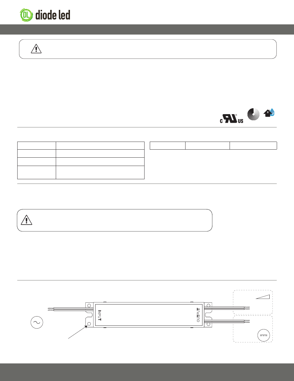
Ensure applicable wire is installed between driver, fixture, and any controls between. When choosing wire, factor in voltage drop, amp rating, and type
to prevent fire or electric shock.
AC/N (White)
AC/L (Black)
V+ (Red)
V− (Blue)
120-277VAC
~
50/60 Hz
To Low Voltage
LED Load
V+ (Purple)
V− (Gray)
To 0-10V
Control/
Dimmer
Attach ground wire to mounting
hole or junction box chassis.
Quick Specs
Installation
Wiring Connections
WARNING
Shock Hazard. May result in serious injury or death.
Turn off power at circuit breaker before installing this product.
Included Models DI-DM-12V60W-0-10V DI-DM-24V100W-0-10V