Questions, Additional resources, System diagram – Diode LED RGB Zone Control User Manual
Page 4
1.877.817.6028
www.DiodeLED.com
www.DiodeLED.com
INSTALLATION GUIDE
4 OF 4
RGB ZONE COLOR CONTROLLER
®
Additional Resources
QUESTIONS?
Visit www.DiodeLED.com or contact Customer Support at [email protected]
or 1.877.817.6028 Monday through Friday, 7:00am - 5:00pm PST.
IG060914-1.2
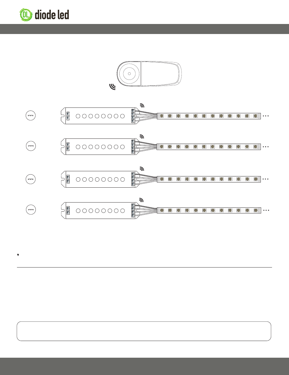
System Diagram
The following diagram is provided as an example system design. Class 2 compliance may require a Class 2 driver per zone receiver (e.g. 60W @ 12V,
96W @ 24V). Install in accordance with the NEC, and local regulations.
Install applicable wire ga
uge / type
RGB Strip Light / Fixture‡‡
RGB Strip Light / Fixture‡‡
RGB Strip Light / Fixture‡‡
RGB Strip Light / Fixture‡‡
DC+
DC-
V+
B
G
R
DC+
DC-
V+
B
G
R
DC+
DC-
V+
B
G
R
DC+
DC-
V+
B
G
R
Zone Receiver****
Zone Remote♦
RF
Zone Receiver****
Zone Receiver****
Zone Receiver****
V+
B
G
R
V+
B
G
R
V+
B
G
R
V+
B
G
R
From 12-24VDC
Class 2 Driver ‡
From 12-24VDC
Class 2 Driver ‡
From 12-24VDC
Class 2 Driver ‡
From 12-24VDC
Class 2 Driver ‡
‡ Refer to driver or controller specifications for a compatible junction box.
‡‡ See fixture specifications for maximum series run limits.
**** Determine the number of low voltage outputs of the driver when installing multiple PWM controllers/dimmer switches. No more than one PWM
controller/dimmer switch can be attached to a single output of the driver.
◊ Zone remote has 10 total zones and may be paired to 10 total receivers (max 1 receiver per zone). Multiple remotes cannot be paired to a single
receiver (max 1 remote per receiver).
Visit the online product page at www.DiodeLED.com for additional product specifications & warranty information.
• RGB Zone Color Controller Specification Sheet
For full specifications.
• Voltage Drop Charts
Use to specify appropriate wire gauge for installation. Available at the ‘Tools & Resources’ page at www.DiodeLED.com.