Mode description chart wiring connections, Troubleshooting – Diode LED RGB Zone Control User Manual
Page 3
1.877.817.6028
www.DiodeLED.com
www.DiodeLED.com
INSTALLATION GUIDE
3 OF 4
RGB ZONE COLOR CONTROLLER
®
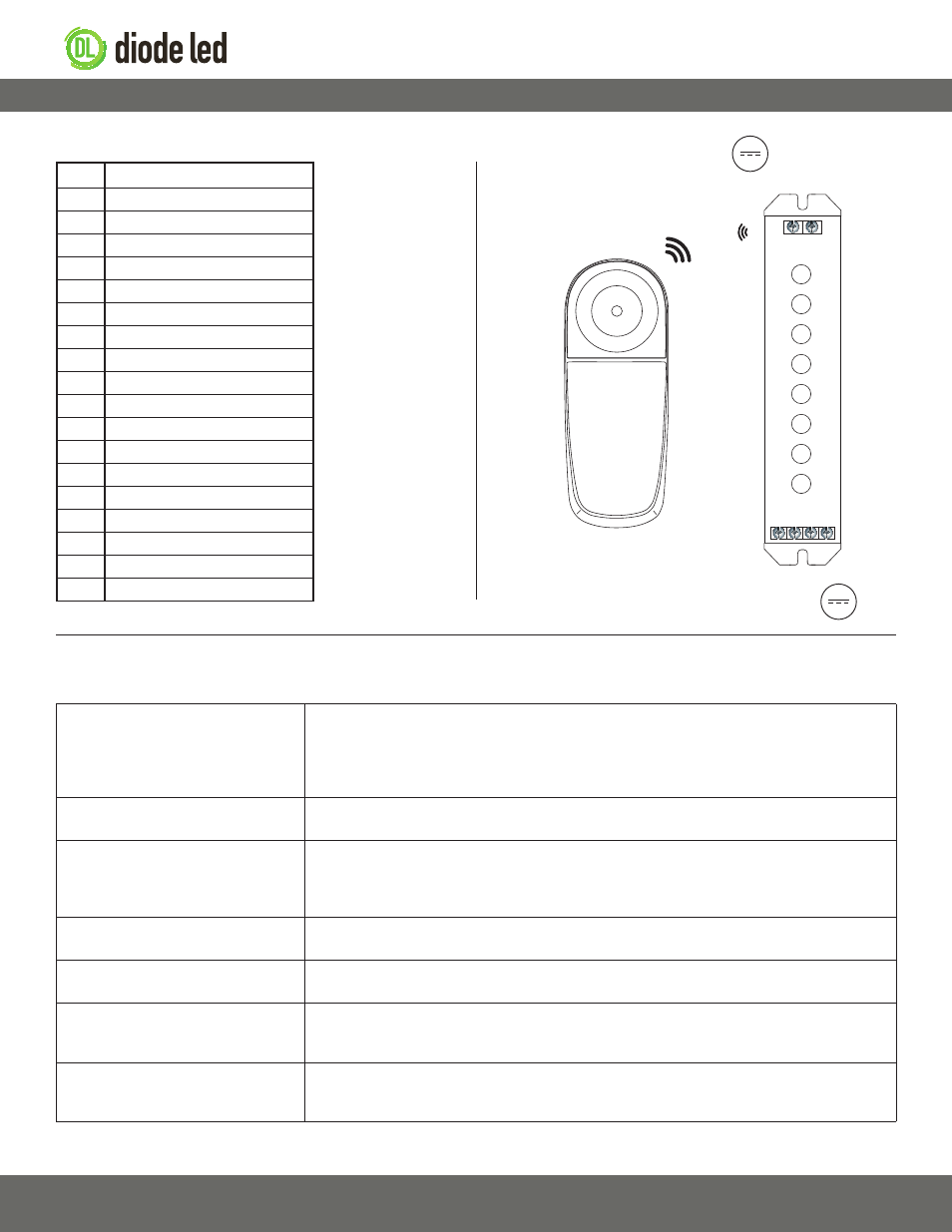
Mode Description Chart
Wiring Connections
No.
Mode
1
3 colors changing
2
7 colors changing
3
White flash
4
7 colors flashing
5
RGB fade in/out
6
Red/Green fade
7
Red/blue fade
8
Green/blue fade
9
Red/yellow fade
10
Green/cyan fade
11
Blue/purple fade
12
Green/yellow fade
13
Blue/cyan fade
14
Red/purple fade
15
Blue/white fade
16
Yellow/purple/cyan fade
17
RGB
18
Full color fade
DO NOT connect directly to 120VAC.
Install in accordance with the NEC,
and local regulations.
DC+
DC-
V+
B
G
R
RF
Input from 12-24V
LED Driver
To Low Voltage
LED Load
Zone R
emot
e
Zone R
eceiv
er
Troubleshooting
Fixture does not illuminate
• See ‘System Diagram’ and installation guides of all components. Ensure the system is wired correctly.
• Verify polarities are correct.
• Ensure a compatible constant voltage dimmable fixture is installed.
• Ensure a compatible constant voltage driver is installed.
• Ensure the driver and fixture have the same voltage specifications (12V & 12V, or 24V & 24V).
Fixture does not dim
• Ensure a compatible constant voltage dimmable fixture is installed.
• Ensure desired zone is selected before changing brightness.
Fixture is flashing or flickering
• Verify a compatible constant voltage driver is installed.
• Ensure a compatible constant voltage dimmable fixture is installed.
• Ensure all connections are properly secured.
• Ensure no more than a single controller is attached to each driver output.
Fixture is slowly flashing
• Ensure driver is not overloaded. An overloaded driver will cause the internal auto-reset of the driver
to trip repeatedly.
Correct colors are not illuminating
• Verify the correct leads are connected to the correct terminals on the receiver.
• Ensure potential leads at opposing end of fixture are not crossed.
Unable to pair remote with receiver
• Ensure the remote is fully charged.
• Read the installation instructions on page 2 thoroughly.
• Reset the receiver(s) to factory settings.
Receivers unintentionally sync together
• If receivers are not paired to a remote, they may unintentionally sync together. To de-sync receivers
see ‘Resetting Receivers to Factory Settings’ on page 2.
Prior to troubleshooting, ensure a compatible system is installed. Verify compatible fixtures, drivers, controls and additional components were specified correctly.
IG060914-1.2