Double led tape light & tray connectors, Troubleshooting – Diode LED Solid Color Tape Light User Manual
Page 4
1.877.817.6028
www.DiodeLED.com
www.DiodeLED.com
INSTALLATION GUIDE
4 OF 6
SOLID COLOR LED TAPE LIGHT
®
IG082514-2.4
Double LED Tape Light & Tray Connectors
Prior to troubleshooting, ensure all items are a compatible system and main power is turned ON.
Troubleshooting
Shift in brightness and/or kelvin
• Review maximum series run limits. Exceeding these limits will cause
excess voltage drop, decreasing brightness and/or kelvin as the run is
extended.
Some LEDs are not functional
• Ensure all connections have been properly attached. Ensure fixture has
not been bent excessively, which may cause components and solder to
detach from the circuit board.
Lights are flickering
• Ensure a compatible driver is installed. Ensure the pre-set mode of the
controller is not on a dynamic mode. Ensure Data +/- connections of
DMX systems are not reversed. If lights continue to flicker, check for
loose connections. Ensure tape light connectors are properly attached.
Lights are turning on/off repeatedly
• Ensure driver is not overloaded. An overloaded driver will trip the
internal auto-reset (of driver) repeatedly, turning the system on/off.
CLICKTIGHT™ Connector Troubleshooting
• Ensure compatible CLICKTIGHT™ models are attached. Tape lights vary
in width and require specific connectors. Contact your supplier for
additional information.
• Tape light is polarity sensitive. Ensure the +/- markings of the CLICKTIGHT™
connector is aligned with the +/- markings of the tape. If polarity is
backwards, reverse the lead wire connection or detach tape from
CLICKTIGHT™ connector and reattach opposing end of tape to connector.
–
+
–
+
–
+
–
+
–
+
–
+
–
+
–
+
–
+
–
+
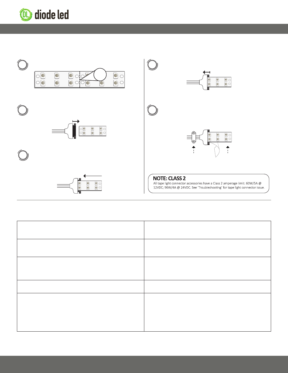
These instructions apply only to Double LED Tray Connectors. Never cut tape attached to a live circuit.
1
2
Cut the tape at the line indicated with the scissors icon.
Squeeze the connector tray firmly with fingers or pliers to
ensure connection.
When ready for mounting, peel off the 3M™ adhesive backing
of the tape and tear off along the connector tray edge. Mount
tape light and utilize a wiring harness to secure lead wires.
Gently pull out the black tab 1-2mm. Note the +/- polarity
markings of the tape light.
Firmly insert the tape light into the connector tray with the
3M™ adhesive backing still intact to the tape. Ensure the
contact/solder points of the tape are completely covered by the
contact sheath.
3
4
5
Cut points not drawn to scale
–
+
–
+
Wiring Harness
3M™ Adhesive