Clicktight, Connectors – Diode LED Solid Color Tape Light User Manual
Page 3
1.877.817.6028
www.DiodeLED.com
www.DiodeLED.com
INSTALLATION GUIDE
3 OF 6
SOLID COLOR LED TAPE LIGHT
®
IG082514-2.4
Cut points not drawn to scale
CLICKTIGHT
™
Connectors
1
2
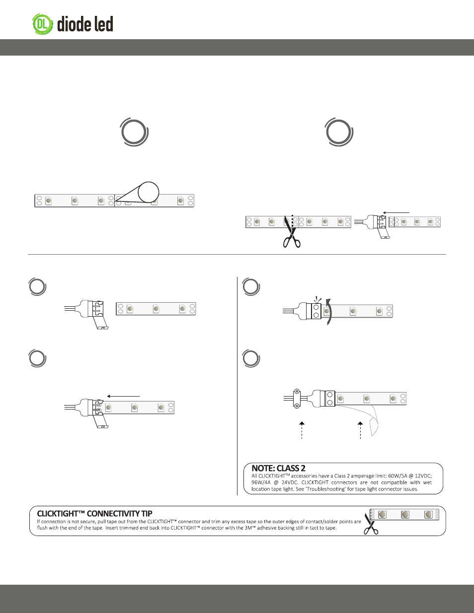
Close the CLICKTIGHT™ latch to ensure connection.
When ready for mounting, peel off the 3M™ adhesive backing
of the tape and tear off along the connector tray edge. Mount
tape light and utilize a wiring harness to secure lead wires.
Open the CLICKTIGHT™ latch and note the +/- polarity markings.
Firmly insert the tape light into the connector tray with the
3M™ adhesive backing still intact to the tape. Ensure the
contact/solder points of the tape are directly underneath the
metal placement tabs of the connector.
3
4
Wiring Harness
3M™ Adhesive
Attaching CLICKTIGHT™ Connectors
–
+
–
+
–
+
–
+
Cutting Tape Light
Cutting tape light densities lower than 2.88W/ft.:
Cut the tape at the cut line indicated with the scissors icon.
Utilizing CLICKTIGHT™ connectors requires specific cutting instructions for high density solid color tape light to achieve a proper connection. See
options A or B (does not apply to RGB tape light). Never cut tape attached to a live circuit. DO NOT solder CLICKTIGHT™ connectors to tape light.
Cutting tape light densities higher than 2.88W/ft.:
DO NOT cut at the scissors icon. Instead, cut the tape along the outside
edge of the LED chip closest to the scissors icon so four contact/solder
points remain intact to the tape. This will ensure the latch of the
CLICKTIGHT™ connector closes properly.
–
+
–
+
–
+
–
+
–
+
–
+
–
+
Tape less than 2.88W/ft.
Tape 2.88W/ft. and higher
–
+
–
+
–
+
–
+
–
+
OR
a
b
–
+
–
+
–
–
+
+