Omnidrive™ electronic dimmable driver, System diagrams – Diode LED OMNIDRIVE User Manual
Page 3
1.877.817.6028
www.DiodeLED.com
www.DiodeLED.com
INSTALLATION GUIDE
3 OF 4
®
OMNIDRIVE™ ELECTRONIC DIMMABLE DRIVER
IG071014-1.1
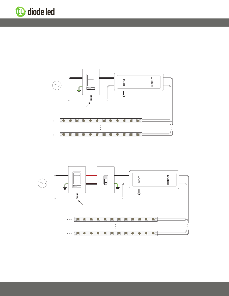
AC Power
50/60Hz
Compatible Dimming Control
or On/Off Switch ^
LED Tape Light / Fixture‡‡
L
Ins
tall applic
able wire
gauge / type
OMNIDRIVE Dimmable Driver ^^
Some dimmers may require an
additional neutral wire connection.
N
N
GND*
N
L
V+
V−
V+
V−
V+
V−
AC Power
50/60Hz
Compatible
Dimming Control ^
LED Tape Light / Fixture‡‡
L
Ins
tall applic
able wire
gauge / type
Some dimmers may require an
additional neutral wire connection.
N
N
GND*
N
L
V+
V−
V+
V−
V+
V−
Traveling
Lines
3-Way On/Off Switch
OMNIDRIVE Dimmable Driver ^^
The following diagrams are provided as example system designs. Always review each component installation guide for detailed and up-to-date wiring
instructions. Install in accordance with NEC and local regulations.
OMNIDRIVE Standard System Diagram
System Diagrams
OMNIDRIVE 3-Way System Diagram
* Driver may not require a fault ground connection. Refer to driver
specifications for additional information.
˄ Install a compatible dimming control or switch. See the ‘Electronic
Dimmable Driver / Dimmer Compatibility List’ for compatible dimming
controls. See the dimming control manufacturer installation guide for
complete wiring instructions.
˄
˄ Ensure to load the driver at least 60% the labeled load for proper
dimming performance (required for dimmable installations only).
‡‡ See fixture specifications for maximum series run limits.