Description, Trusted, Tmr module t8160 – Rockwell Automation T8160 Trusted TMR Interface User Manual
Page 9
Trusted
TM
TMR Module T8160
Issue 13 May 13
PD-T8160
9
1. Description
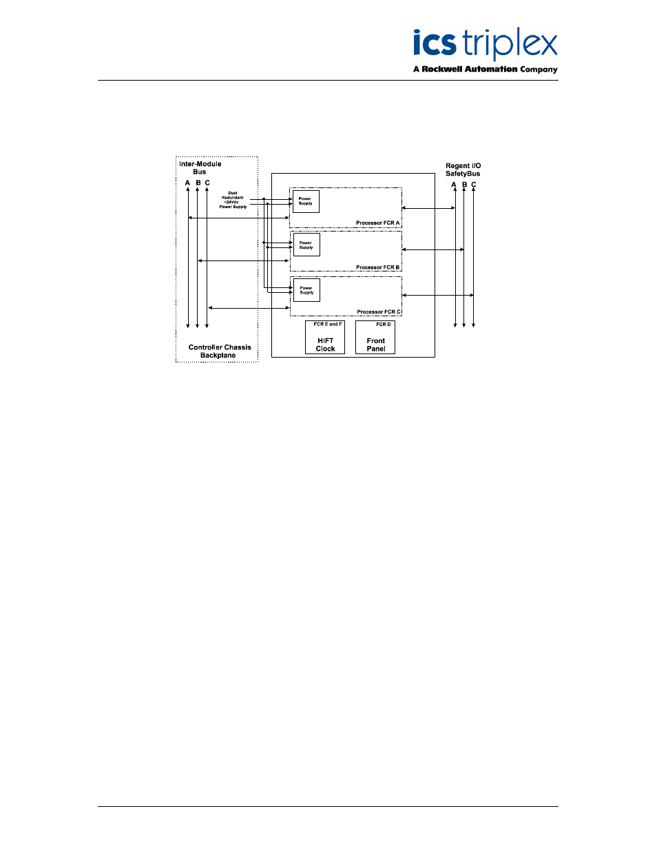
Figure 1 shows a block diagram of the Trusted
TM
TMR Interface.
Figure 1 Block Diagram of the Trusted
TM
TMR Interface
The Trusted
TM
TMR Interface is a Triple Modular Redundant (TMR), fault tolerant design containing six
fault containment regions (FCR):
1. FCRs A, B, and C are processor sub-systems, each containing a processor, an I/O
Processor logic unit, a Bus Interface, an I/O Safetybus interface and a power supply. The
processor sub-systems work in lock-step synchronisation with each other.
2. FCR D is the front panel interface.
3. FCRs E and F are the master and secondary master oscillators of the HIFT system clocks.
Each module processor sub-system has interfaces to the Inter-Module Bus and the Regent I/O
Safetybus. These interfaces consist of an input voter, discrepancy detector logic, and an output driver.
The voting and fault detection circuits allow the processor sub-systems to identify and isolate transient,
intermittent, and permanent faults as they occur. All faults are recorded in the system’s fault history.
The module’s triplicated processor and Regent+Plus I/O interfaces ensure that no failure in the module
will affect the operation of Trusted
TM
or Regent+Plus systems.
The triplicated power supply unit receives dual redundant +24V dc from the Controller chassis
backplane, and converts the supply to the logic levels required by the module circuits. The module is
capable of operating with a failure of either of the redundant power feeds.
The Trusted
TM
TMR Interface has three external interfaces:
1. Trusted
TM
Inter-Module Bus. Triplicated, high-speed interface to the Trusted
TM
TMR
Processor.
2. Regent I/O Safetybus Interface. Fully triplicated, synchronised RS-485, 8-bit parallel data with
clock and sync signals to the Regent and Regent+Plus I/O sub-system.
3. Front Panel Facilities. Status and fault indicators.