Front panel description, Figure 2.17 setpoint multiplication connection, Attention – Rockwell Automation 1440-PK02-05M2 XM-720 Machine Monitor User Manual
Page 31
Publication GMSI10-UM001C-EN-E - June 2011
Installing the XM-720 Machine Monitor 31
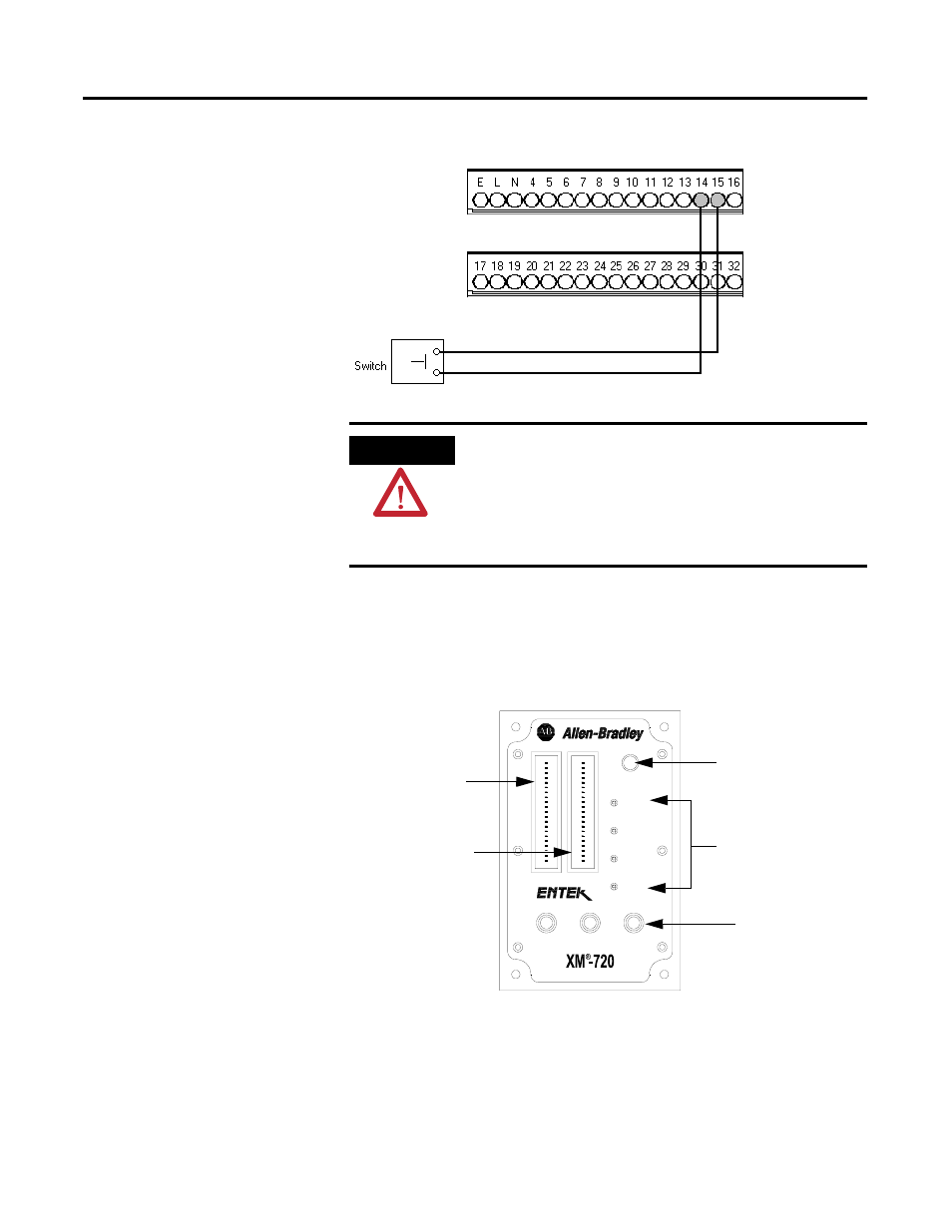
Figure 2.17 Setpoint Multiplication Connection
Front Panel Description
The XM-720 monitor front panel consists of four LEDs, two easy to read
digital meters, three BNC connectors and a Reset Relay switch.
Figure 2.18 XM-720 Front Panel
ATTENTION
The switch input power supply must be grounded at a
single point. Connect the Switch Return signal to chassis or
earth ground at either the XM-720 system, the switch, or
other equipment that is wired to this switch. If grounding
at the XM-720 system, place a jumper between the Switch
RTN terminal and any available Chassis GND terminal.
Warning
Trip
Module
Fault
Xdcr
Fault
Reset
Tacho
CH 2
CH 1
0
25
50
75
%
100
0
25
50
75
%
100
LED indicators
BNC connectors for
output of buffered
input signals
Channel 1 meter
showing overall
measurement
Channel 2 meter
showing overall
measurement
Relay reset switch