Connecting the 4-20ma outputs – Rockwell Automation 1440-PK02-05M2 XM-720 Machine Monitor User Manual
Page 29
Publication GMSI10-UM001C-EN-E - June 2011
Installing the XM-720 Machine Monitor 29
Connecting a Hall Effect Tachometer Sensor
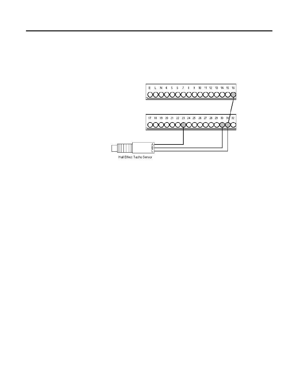
Figure 2.15 shows the wiring of a Hall Effect Tachometer Sensor,
Cat. No. 44393, to the XM-720 back panel.
Figure 2.15 Hall Effect Tachometer Signal Connection
Connecting the 4-20mA Outputs
The XM-720 monitor includes an isolated 4-20mA per channel output into a
maximum load of 250 ohms. In the provided configuration files, the 4-20mA
output signals track the overall measurement, and the Min and Max range is set
according to the type of transducer.
The measurements that the 4-20mA tracks and the signal levels that
correspond to the 4mA and 20mA can be changed using the XM Serial
Configuration Utility. Refer to 4-20mA Output Parameters on page 50 for
details.
Wire the 4-20mA outputs to the XM-720 back panel as shown in Figure 2.16.