Cutout dimension, Panel cutout, Figure 2.1 mounting dimensions and side view – Rockwell Automation 1440-PK02-05M2 XM-720 Machine Monitor User Manual
Page 12: Figure 2.2 cutout dimensions
Publication GMSI10-UM001C-EN-E - June 2011
12 Installing the XM-720 Machine Monitor
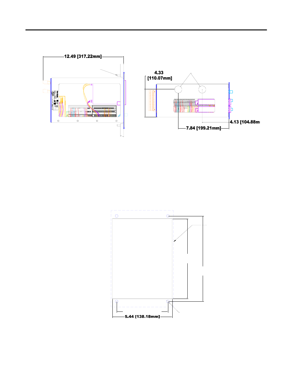
Figure 2.1 Mounting Dimensions and Side View
Cutout Dimension
Use the full size template shipped with the XM-720 monitor to mark the
cutout dimensions. The figure below shows a reduced scale cutout.
Figure 2.2 Cutout Dimensions
1 2 3 4 5 6 7 8 9 10
0
1617 18 19 2021 22 2324 25 2627 28 2930 31 3233
34 35 3637 38 39 40 4142 434445 4647 48 495051
111213 14 15
1 2 3 4 5 6 7 8 9 10
0
1617 18 19 2021 22 23 24 252627 282930 31 3233
34 35 3637 38 39 40 41 42 4344 45 4647 48 495051
111213 1415
1/4" MOUNTING
SCREWS 4 PLACES
KNOCKOUTS FOR 3/4"
CONDUIT FITTINGS
LOCATED IN TOP OF CASE.
FRONT PANEL
PANEL
CUTOUT
7.25
[184.15mm]
7.75
[196.85mm]
4.650 [118.11mm]
Ø.26
4 PLACES
This manual is related to the following products: