Rockwell Automation 1440-PK02-05M2 XM-720 Machine Monitor User Manual
Page 17
Publication GMSI10-UM001C-EN-E - June 2011
Installing the XM-720 Machine Monitor 17
The XM-720 back panel terminal block is equipped with three single-pole,
double-throw relays. Figures 2.5 to 2.7 show the connection for the three
relays.
Module/Transducer Fault Relay
In the provided configuration files, the Fault relay is configured to be a failsafe
relay and is set up to activate if any one of the conditions occurs:
• There is a hardware or firmware failure.
• A transducer fault is detected on the associated transducer.
You can change the alarms associated with this relay as well as the behavior of
the relay using the XM Serial Configuration Utility. Refer to Editing the
XM-720 Parameters on page 44 for more information.
Figure 2.5 shows the on-board relay connection for the Fault relay.
Figure 2.5 Wiring Connection for Fault Relay (Failsafe)
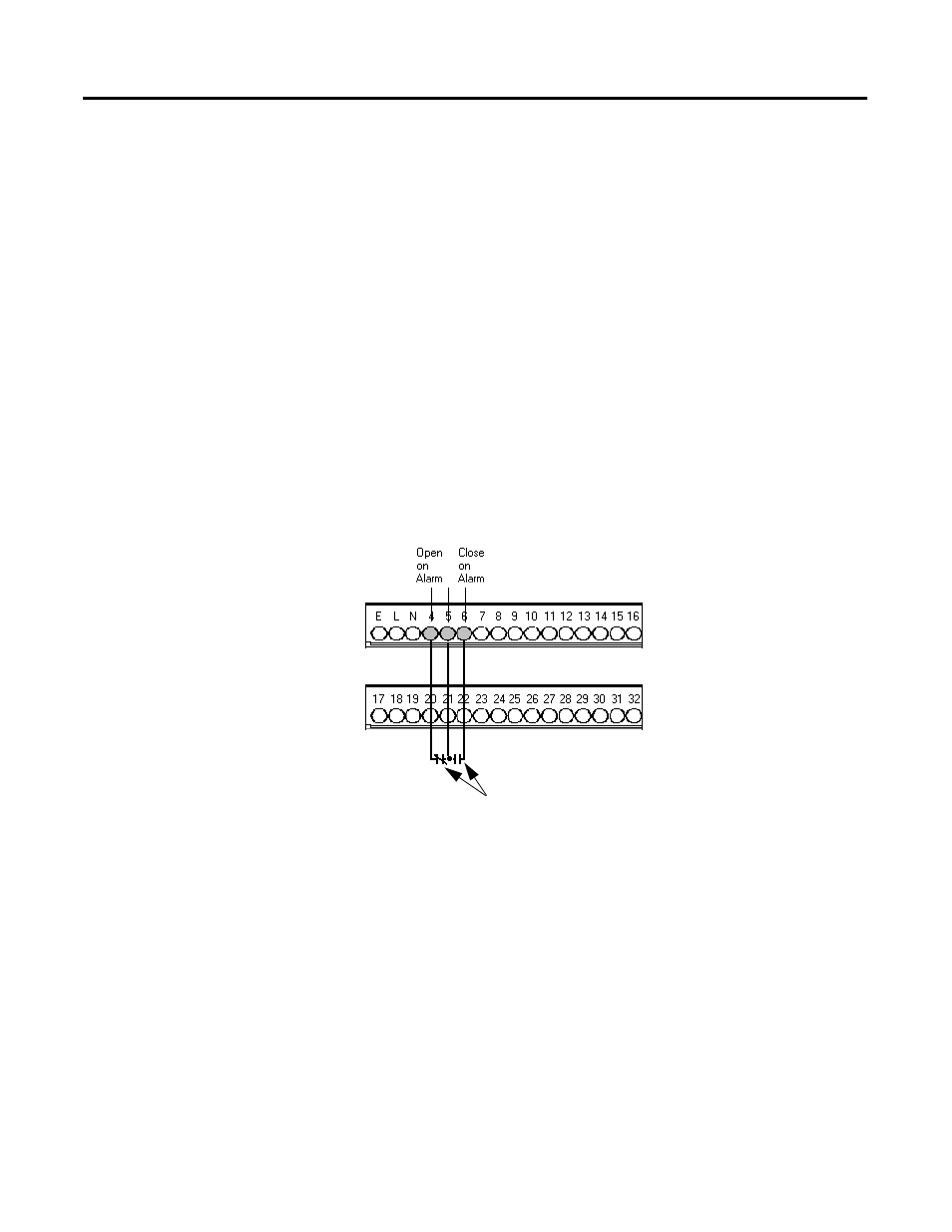
Warning Relay
In the provided configuration files, the Warning relay is configured to activate
when the overall measurement in either channel exceeds the alert threshold
levels (same conditions that activate the Warning LED). This relay is
configured as a non-failsafe relay. Figure 2.6 shows the on-board relay
connection for the Warning relay.
The alert threshold levels and the behavior of the relay can be changed using
the XM Serial Configuration Utility. Refer to Editing the XM-720 Parameters
on page 44.
Shown with power on
and no fault